
Support frame for pellicles

A technology of supporting frame and skin, which is applied in the direction of originals, optics, instruments, etc. used for photomechanical processing, can solve the problems of circuit pattern offset and other problems, and achieve the effect of reducing processing amount, reducing processing amount, and easy processing

Inactive Publication Date: 2017-09-26
NIPPON LIGHT METAL CO LTD
View PDF6 Cites 0 Cited by
  • Summary
  • Abstract
  • Description
  • Claims
  • Application Information

AI Technical Summary

Problems solved by technology

However, since the supporting frame generates a restoring force to return to the original warped shape, when the restoring force is large, the transparent substrate is also warped following the deformation of the supporting frame.
[0006] In addition, if distortion occurs on the transparent substrate, there is a problem that the circuit pattern is shifted from the correct position when transferring the circuit pattern on the transparent substrate to the protective layer on the wafer.

Method used


Image

  • Support frame for pellicles
  • Support frame for pellicles
  • Support frame for pellicles

Examples


Embodiment Construction

[0038] Embodiments of the present invention will be described in detail with reference to the drawings as appropriate.

[0039] In addition, in each drawing of this embodiment, in order to demonstrate the structure of a support frame easily, each part of a support frame is shown schematically moderately.

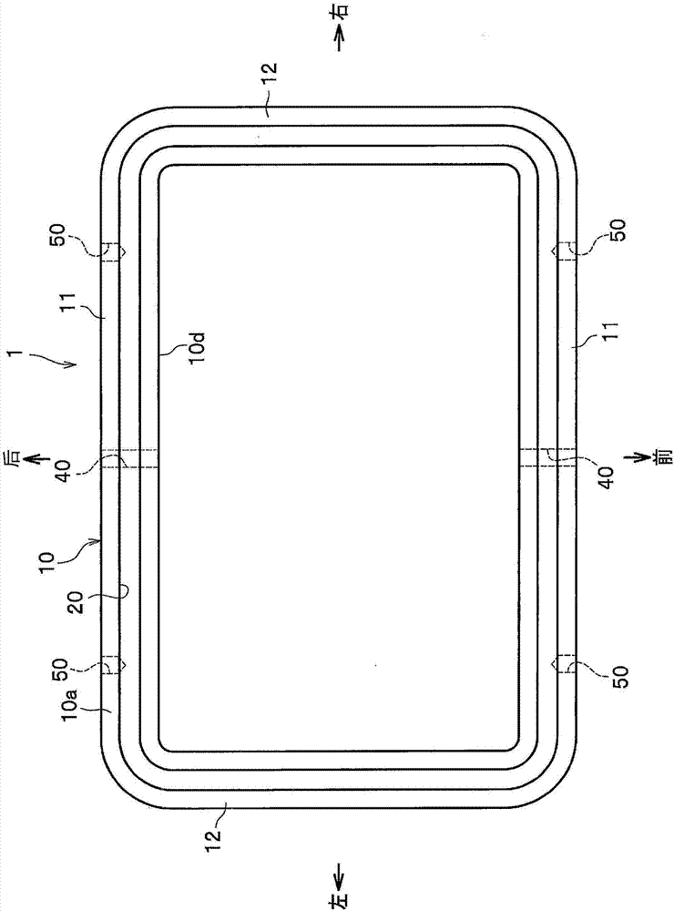
[0040] In the following description, front, rear, left, right, front, and back are set for easy understanding of the support frame, and do not limit the structure and use state of the support frame.

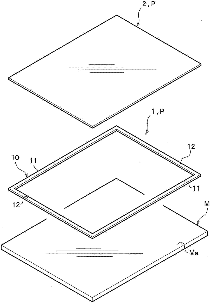
[0041] like figure 1 As shown, the support frame 1 of this embodiment is a member used for the skin P used in the manufacturing process of an integrated circuit. The skin P is a dustproof cover for preventing dust and the like from adhering to the front surface Ma of the transparent substrate M (photomask).

[0042] The skin P includes: a supporting frame 1 that surrounds the entire circuit pattern (not shown) drawn on the transparent substrate M; and a skin coating 2 that co...


PUM

PropertyMeasurementUnit
heightaaaaaaaaaa
depthaaaaaaaaaa
heightaaaaaaaaaa

Abstract

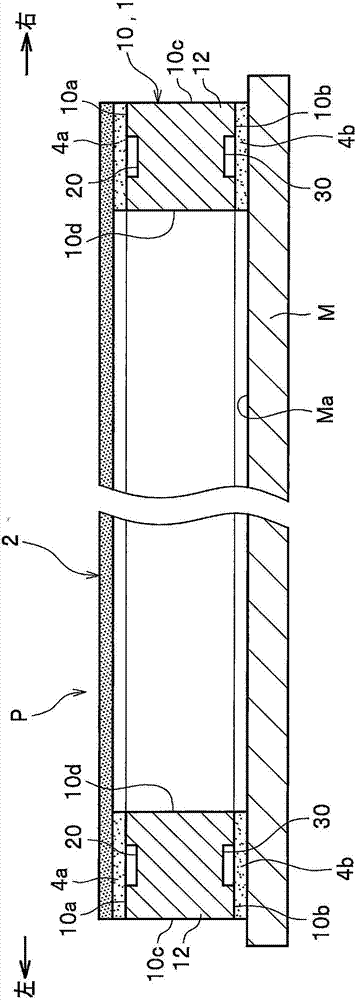
This support frame (1) has a frame body (10) that is formed of an aluminum alloy. A pellicle film (2) is bonded to a front surface (10a) of the frame body (10), and a transparent substrate (M) is bonded to a back surface (10b) of the frame body (10). The height of the frame body (10) in the front-back direction is from 1 mm to 6 mm (inclusive). Recessed grooves (20, 30) are formed in the front surface (10a) and the back surface (10b) of the frame body (10), and the recessed grooves (20, 30) are formed to have a depth of 0.2 mm or more. Due to this configuration, the support frame (1) is easily processed, and deformation of the transparent substrate (M) at the time of bonding of the support frame (1) to the transparent substrate (M) is able to be prevented.

Description

technical field [0001] The present invention relates to a support frame for epidermis. Background technique [0002] The manufacturing process of an integrated circuit includes a photolithography process in which a circuit pattern drawn on a transparent substrate called a photomask and reticle is transferred to a protective layer coated on a wafer. [0003] In the above-mentioned photolithography process, if foreign matter such as dust adheres to the transparent substrate, the circuit pattern transferred to the protective layer becomes unclear. Therefore, the transparent substrate is covered with a dust cap called a skin. [0004] The skin includes: a support frame that surrounds the entirety of the circuit pattern drawn on the transparent substrate; and a light-transmitting skin film that covers the front surface of the support frame. The back of the support frame is bonded to the transparent substrate. [0005] The above-mentioned support frame may be twisted in the fron...

Claims


Application Information

Patent Timeline
Patent Type & Authority Applications(China)
IPC IPC(8): G03F1/64B65D85/86H01L21/027
CPCH01L21/027G03F1/64G03F1/66H01L21/0274
Inventor 石户伸幸
Owner NIPPON LIGHT METAL CO LTD
Learn More