
Method of manufacturing trim

A manufacturing method and decorative strip technology, applied in metal rolling, metal rolling, sealing devices, etc., can solve problems such as waste and poor yield, and achieve the effects of reducing deviation, ensuring rigidity, and improving rigidity

Active Publication Date: 2014-11-05
TOKAI KOGYO CO LTD
View PDF12 Cites 0 Cited by
  • Summary
  • Abstract
  • Description
  • Claims
  • Application Information

AI Technical Summary

Problems solved by technology

[0006] However, in the case of punching and forming gaps (or slits) on a strip-shaped metal plate by press working, the punched out part in the strip-shaped metal plate becomes an unnecessary part. Wasteful and therefore has the disadvantage of not being very good yield

Method used


Image

  • Method of manufacturing trim
  • Method of manufacturing trim
  • Method of manufacturing trim

Examples


Embodiment Construction

[0078] Next, an embodiment in which a mode for carrying out the present invention has been embodied will be described.

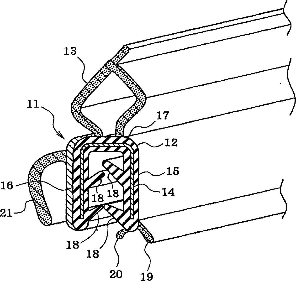
[0079] Such as figure 1 As shown, with regard to the long trim 11 (so-called trunk sealing trim) installed on the flange (not shown) of the trunk opening edge of the body panel of the automobile or the like, rubber or thermoplastic synthetic resin (including Thermoplastic Elastomer) and other elastic polymer materials are extruded to integrally form the mounting part 12 with a U-shaped cross-section and the cylindrical hollow sealing part 13 made of sponge rubber or soft TPE material, and then insert and extrude Molding (also referred to as co-extrusion molding) embeds the core material 14 formed of a band-shaped metal plate in the mounting portion 12 .

[0080] The mounting portion 12 has a vehicle exterior side wall portion 15, a vehicle interior side wall portion 16, and a bottom wall portion 17 connecting the two side wall portions 15 and 16. On the out...


PUM

PropertyMeasurementUnit
Rockwell hardnessaaaaaaaaaa
Vickers hardnessaaaaaaaaaa

Abstract

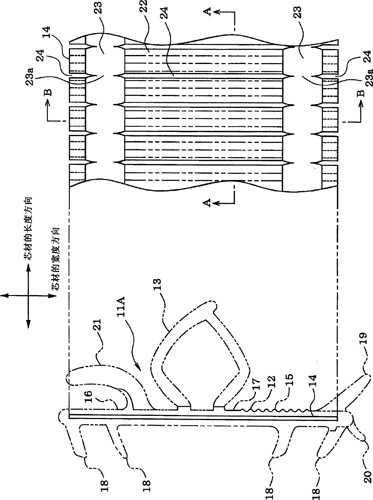
A method of manufacturing an elongated core which is buried in an elongated trim. The method includes, forming slits to a metal plate, which extend in a second direction, at predetermined intervals in a first direction so as to form core pieces between the adjacent slits; and rolling a portion of the metal plate in which the slits are not formed in the second direction to form a rolled portion extending in the first direction, and expanding the slits in the first direction to form spaces, thereby preparing a primary core in which the core pieces and the spaces are alternately provided in the first direction. Additionally, the method includes, supplying the primary core to between a pair of deformed portion forming rollers engaged with each other such that reinforcing defaulted portions extending in the second direction are repetitively formed in the first direction.

Description

technical field [0001] The present invention relates to a method for manufacturing a long core material embedded in a long decorative strip made of a polymer material, a method for producing a decorative strip, and a core material. Background technique [0002] Generally, on the flanges of the door opening edges of vehicles such as automobiles and the opening edges of trunks and hatchbacks, a long decorative strip along the flanges is attached. The decorative strip is extruded into a shape having a substantially U-shaped mounting portion in cross section using polymer materials such as rubber, thermoplastic synthetic resin (including thermoplastic elastomer), and by using the substantially U-shaped mounting portion Fix to the flange by clamping the flange of the opening edge from both sides. Such a decorative strip is installed as follows: a long reinforcing core material (for example, a core material formed of a strip-shaped metal plate such as a cold-rolled steel plate) h...

Claims


Application Information

Patent Timeline
Patent Type & Authority Patents(China)
IPC IPC(8): B60R13/06B60J10/08B21B1/08B21H8/00
CPCB60J10/08B60J10/0065B60J10/0011B60J10/18B60J10/32B60J10/80Y10T29/49986Y10T428/24628
Inventor 广江惠治
Owner TOKAI KOGYO CO LTD
Learn More