HILS (hardware-in-the-loop simulation) test bed for electromechanical brake booster and testing method
An electro-mechanical braking and test-bed technology, applied in the testing of mechanical parts, the testing of machine/structural parts, instruments, etc., can solve problems such as the inability of electro-mechanical booster test algorithms to improve the subjective evaluation of pedal feel, so as to improve performance. Efficiency and real-time, good repeatability, high simulation effect
Active Publication Date: 2017-09-26
JILIN UNIV
View PDF14 Cites 17 Cited by
- Summary
- Abstract
- Description
- Claims
- Application Information
AI Technical Summary
Problems solved by technology
The electromechanical brake booster hardware-in-the-loop simulation test bench and test method solve the shortcomings that the existing test be
Method used
View moreImage
Smart ImageViewing Examples
Examples
 PUM
 Abstract
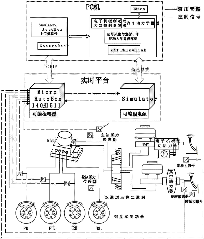
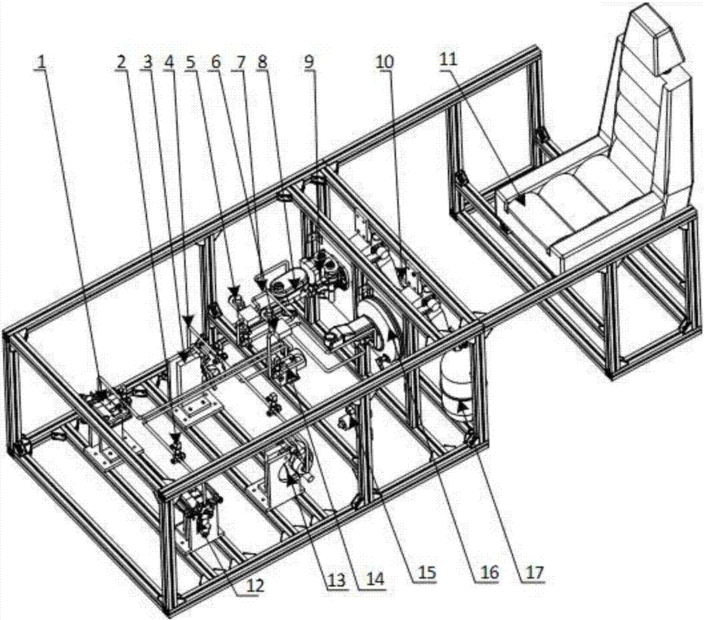
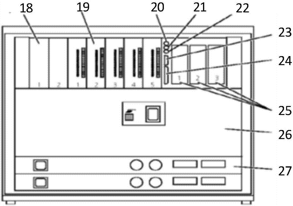
The invention belongs to the field of semi-physical simulation tests, and particularly provides an HILS (hardware-in-the-loop simulation) test bed for an electromechanical brake booster and a testing method. The test bed comprises a PC (personal computer), a real-time simulation platform, a hardware platform and a signal collection and emission platform, wherein the PC is connected with the real-time simulation platform through a high-speed special bus with a cable serving as a medium; the signal collection and emission platform is connected with the PC on the basis of a TCP/IP (transmission control protocol/internet protocol) through a local area network and performs signal communication with the hardware platform through a sensor. The HILS test bed is a real-time simulation platform unit, tests of hardware of the electromechanical brake booster, an automobile dynamics simulation model, an ESP (electronic stability program) of an automobile and actuator equipment in a simulation loop can be realized, and the problem that an existing test stand cannot perform testing, calibration, algorithm improvement and subjective assessment of pedal feeling on the electromechanical brake booster in a concentrated manner is solved.
Description
technical field [0001] The invention belongs to the field of semi-physical simulation tests, in particular to a hardware-in-the-loop simulation test bench and a test method for an electromechanical brake booster. Background technique [0002] The continuous improvement of people's requirements for automobile performance has led to the continuous innovation of auto parts technology, and the automobile braking system is a necessary guarantee for safety, environmental protection, and intelligence. Traditional vacuum booster devices can no longer meet these needs. What emerged at the historic moment was a braking system based on an electromechanical booster. From the point of view of structural characteristics, it abandons the traditional vacuum booster, and replaces the vacuum source with motor power as a booster source to meet the braking requirements of electric vehicles. From the perspective of functional characteristics, the braking system with electromechanical booster re...
Claims
Login to View More Application Information
Patent Timeline
 IPC IPC(8): G01M13/00
CPCG01M13/00Y02P90/02
Inventor 吴坚陈朋成马秀丹刘迪
Owner JILIN UNIV
Features
- R&D
- Intellectual Property
- Life Sciences
- Materials
- Tech Scout
- Unparalleled Data Quality
- Higher Quality Content
- 60% Fewer Hallucinations
Learn More Browse by: Latest US Patents, China's latest patents, Technical Efficacy Thesaurus, Application Domain, Technology Topic, Popular Technical Reports.
© 2025 PatSnap. All rights reserved.Legal|Privacy policy|Modern Slavery Act Transparency Statement|Sitemap|About US| Contact US: help@patsnap.com


