
Combined energy dissipater suitable for high-head and low-flow flood discharge and energy dissipation

A small flow, high water head technology, applied in water conservancy projects, sea area projects, coastline protection, etc., can solve the problems of good energy dissipation effect, large flood discharge drop, and inconspicuous effect, so as to facilitate construction, improve energy dissipation rate, and benefit Effects of impact and friction

Active Publication Date: 2017-09-22
KUNMING UNIV OF SCI & TECH
View PDF15 Cites 1 Cited by
  • Summary
  • Abstract
  • Description
  • Claims
  • Application Information

AI Technical Summary

Problems solved by technology

However, many rivers have small flow rates and large flood discharge drop, and the downstream scouring damage of rivers intercepted by water conservancy projects is still relatively serious
Using energy dissipators for energy dissipation and anti-scouring, due to high water head and small flow, large energy dissipators have good energy dissipation effect but are not economical; small energy dissipators are economical but the effect is not obvious
Moreover, the energy dissipators of the traditional wide-tail pier are all contraction type, which increases the local erosion in the flood discharge energy dissipation with high water head and small flow.

Method used


Image

  • Combined energy dissipater suitable for high-head and low-flow flood discharge and energy dissipation
  • Combined energy dissipater suitable for high-head and low-flow flood discharge and energy dissipation
  • Combined energy dissipater suitable for high-head and low-flow flood discharge and energy dissipation

Examples


Embodiment 1

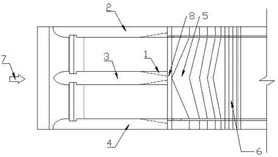
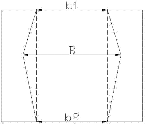
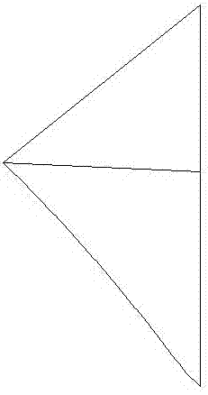
[0017] Embodiment 1: as Figure 1-6 As shown, a combined energy dissipation device suitable for flood discharge and energy dissipation with high water head and small flow, including wide tail pier 1, left pier 2, middle pier 3, right pier 4, stepped energy dissipation transition section 5, and stepped energy dissipation uniform section 6 , aerated ridge 8, inverted "V"-shaped ladder, the left pier 2, middle pier 3 and right pier 4 are located on the WES curved surface of the dam body, and the left pier 2, middle pier 3 and right pier 4 are all provided with wide tail pier 1. The wide-tailed pier 1 is a diffused wide-tailed pier. There is an aeration ridge 8 under the wide-tailed pier 1. The other end of the aeration ridge 8 is connected to the inverted "V"-shaped ladder. Part of it is a stepped energy dissipation transition section 5, and the lower part is a stepped energy dissipation uniform section 6, and the stepped energy dissipation transition section 5 is in the shape of...

example 1

[0023] Example 1: Ahai Hydropower Station adopts the integrated energy dissipation method of traditional Y-shaped wide tail pier + stepped overflow dam + stilling basin for energy dissipation and anti-scouring. Serious erosion of the steps and potential safety hazards of the dam body were eliminated. After reviewing a large number of technical materials, the Ahai Power Station uses 5 holes to discharge the flow, and the peak flow rate of the 5000-year flood reaches 17500 m 3 / s, once in 1000 flood peak flow reaches 15300 m 3 / s, the once-in-100-year flood peak flow reaches 12,200 m 3 / s, belongs to high water head and large flow power station. In the 1:60 hydraulic model experiment, it was found that the Y-shaped wide-tailed pier caused increased negative pressure on the steps, serious cavitation and cavitation when the water flow was contracted, and the energy dissipation of the steps was not fully utilized. The overall energy dissipation effect has a greater impact.

[0...


PUM


Abstract

The invention discloses a combined energy dissipater suitable for high-head and low-flow flood discharge and energy dissipation, and belongs to the field of flood discharge and energy dissipation for water conservancy projects. The combined energy dissipater comprises flaring gate piers, a left abutment pier, a central pier, a right abutment pier, a stepped energy dissipation transition section, a stepped energy dissipation homogenization section, an aerator and an inverted-V-shaped step, wherein the left abutment pier, the central pier and the right abutment pier are located on a WES curved surface of a dam body; the flaring gate piers are arranged below the left abutment pier, the central pier and the right abutment pier separately; the flaring gate piers are diffusing-type flaring gate piers; the aerator is arranged below the flaring gate piers, and the other end of the aerator is connected with the inverted-V-shaped step; and the upper part of the inverted-V-shaped step is the stepped energy dissipation transition section, the lower part of the inverted-V-shaped step is the stepped energy dissipation homogenization section, and the stepped energy dissipation transition section is in an inverted-V shape. According to the combined energy dissipater disclosed by the invention, the diffusing-type flaring gate piers are beneficial to the diffusion and collision of water flow, and the friction of the water flow in air in the high-head and low-flow flood discharge and energy dissipation; and the inverted-V-shaped stepped energy dissipater optimizes the flow state of the water flow, lowers the height of 'water wing', is convenient to construct and saves cost.

Description

technical field [0001] The invention relates to a combined energy dissipator suitable for flood discharge and energy dissipation with high water head and small flow, and belongs to the field of flood discharge and energy dissipation of hydraulic engineering. Background technique [0002] Southwest my country is rich in rivers and abundant rainfall, which is easy for the development and construction of water conservancy projects. However, many rivers have relatively small flow rates and large flood discharge drop, and the scouring damage to the downstream of the intercepted rivers by water conservancy projects is still relatively serious. Using energy dissipators for energy dissipation and anti-scouring, due to the high water head and small flow, large energy dissipators have good energy dissipation effects but are uneconomical; small energy dissipators are economical but the effect is not obvious. Moreover, the energy dissipators of the traditional wide-tail pier are all co...

Claims


Application Information

Patent Timeline
IPC IPC(8): E02B8/06
CPCE02B8/06
Inventor 杨具瑞李书曌
Owner KUNMING UNIV OF SCI & TECH
Learn More