Oil-immersion conveyor

A conveyor and conveying mechanism technology, applied in the direction of liquid injection device, pretreatment surface, injection device, etc., can solve the problems of product bruising, low efficiency, product quality decline, etc., to avoid product damage and waste, and improve product quality , fully oiled effect

Pending Publication Date: 2017-09-22
南京力旷机电科技有限公司
View PDF5 Cites 3 Cited by
  • Summary
  • Abstract
  • Description
  • Claims
  • Application Information

AI Technical Summary

Problems solved by technology

However, this process has the following disadvantages and deficiencies in industrial production: 1. Pouring products in batches into the oil tank will cause bumps between products, resulting in product bruises, product quality decline, and reject rate increase
2. Due to manual operation, people will inevitably come into contact with oil, which will affect the occupational health of operators
3. Due to the use of manual operation, its efficiency is relatively low, and automatic continuous production cannot be realized
4. Due to the use of the oil tank, its open structure leads to inevitable oil leakage, resulting in oil pollution on the production site, which has an impact on environmental pollution
5. Due to the use of the oil tank, the oil residue on the surface of the product cannot be cleaned, resulting in unnecessary waste and pollution
6. The method of using the oil tank to immerse oil cannot guarantee that the fine areas such as the slit of the workpiece can be effectively immersed in oil, resulting in the most precise part of the product being unable to be protected by oil immersion

Method used


Image

  • Oil-immersion conveyor
  • Oil-immersion conveyor

Examples


Embodiment 1

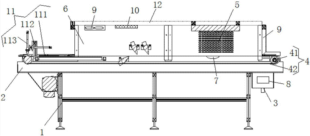
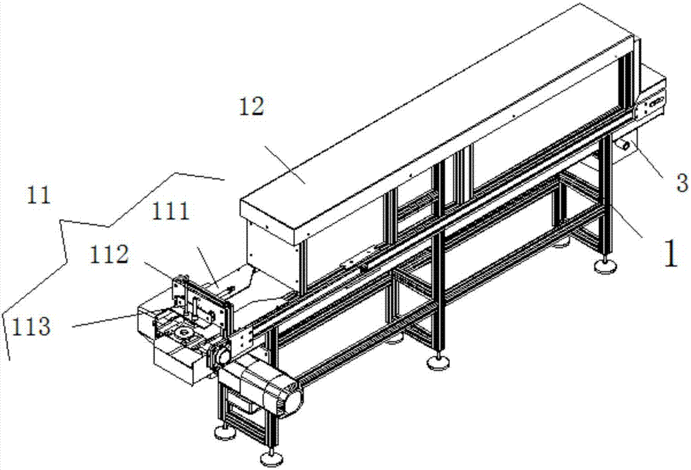
[0020] An oil-immersed conveyor, comprising a frame 1, the upper end of the frame 1 is fixedly provided with an oil receiving tank 2, an oil tank 3 is installed on the right side of the oil receiving tank 2, and an oil well pump 8 is installed in the oil tank 3, the An oil injection delivery mechanism 4 is installed above the oil tank 3, and the oil injection delivery mechanism 4 includes a motor 41 and a conveyor belt 42, the motor 41 is connected to the conveyor belt 42 through a rotating shaft, and the upper rear portion of the frame 4 is provided with The oil baffle 6, the right end of the oil baffle 6 is located on the top of the conveyor belt 42 and is provided with a spray system 5, and the bottom of the spray system 5 is located in the middle of the conveyor belt 42 and an ultrasonic vibrator 7 is installed. The oil baffle 6 A circulating fan 9 and a heating system 10 are installed on the top of the conveyor belt 42 at the left end of the conveyor belt 42, and a pusher ...


PUM


Abstract

The invention discloses an oil-immersion conveyor. The oil-immersion conveyor comprises a rack, an oil receiving groove is fixedly arranged on the upper end of the rack, an oil groove is mounted on the right side of the oil receiving groove, and an oil pump is mounted in the oil groove; an oil-spraying conveying mechanism is mounted above the oil groove and comprises a motor and a conveying belt, the motor is connected with the conveying belt through a rotary shaft, an oil baffle plate is arranged on the rear portion of the upper end of the rack, and a spraying system is arranged on the position, located above the conveying belt, of the right end of the oil baffle plate; and an ultrasonic vibrator is mounted on the position, located in the middle of the conveying belt, below the spraying system, a circulating fan and a heating system are mounted on the position, located above the conveying belt, of the left end of the oil baffle plate, and a material pushing system is mounted on the left side of the conveying belt. According to the oil-immersion conveyor, parts enter the oil-spraying conveyor, the conveyor detects the parts entering the conveyor, an oil-spraying pump works, a layer of working oil layer is formed on the surface of each part, under further working of the ultrasonic vibrator, the surfaces of the parts are fully covered with oil liquid, and moreover no bubble is generated and oil distributing is even.

Description

technical field [0001] The invention relates to the technical field of conveyors, in particular to an oil-immersed conveyor. Background technique [0002] At present, in the production process of basic processing, it is necessary to carry out anti-rust treatment on products. Oil immersion is a common and traditional process for anti-rust, but most of the traditional oil immersion processes use the oil tank method, which is to pour the workpiece into the oil tank. After a period of time, the workpiece is pulled out from the oil tank, so that the surface of the workpiece will adhere to the oil to achieve the purpose of oil immersion. But this process has the following shortcomings and deficiencies in industrialized production: 1. Pouring products in batches into the oil tank will cause bumps between products, resulting in product bumps, product quality decline, and reject rate increase. 2. Due to manual operation, people will inevitably come into contact with oil, which will ...

Claims


Application Information

Patent Timeline
IPC IPC(8): B05B15/12B05B9/04B05B17/06B05B13/02B05D3/04
CPCB05B9/0403B05B13/0221B05B17/06B05D3/0406
Inventor 江慧张勋
Owner 南京力旷机电科技有限公司
Why Eureka
Try Eureka