
Engine crankshaft circular bead laser cladding repairing device and method

A laser cladding and engine technology, applied in laser welding equipment, metal processing equipment, welding equipment, etc., can solve problems such as difficult repair of crankshaft rounded corners and difficult processing of rounded corners, and achieve good results

Active Publication Date: 2017-09-19
SHANDONG UNIV
View PDF7 Cites 6 Cited by
  • Summary
  • Abstract
  • Description
  • Claims
  • Application Information

AI Technical Summary

Problems solved by technology

[0003] At present, most of the engine crankshaft laser cladding repair is to repair the journal, but it is difficult to repair the crankshaft fillet
This is because for a laser with a three-axis motion structure, the crankshaft fillet is limited by the structure, the laser head is parallel to the repair plane, the powder and the laser beam cannot touch the fillet, and the fillet is difficult to process

Method used


Image

  • Engine crankshaft circular bead laser cladding repairing device and method
  • Engine crankshaft circular bead laser cladding repairing device and method
  • Engine crankshaft circular bead laser cladding repairing device and method

Examples


Embodiment Construction

[0038] It should be pointed out that the following detailed description is exemplary and intended to provide further explanation to the present application. Unless defined otherwise, all technical and scientific terms used herein have the same meaning as commonly understood by one of ordinary skill in the art to which this application belongs.

[0039] It should be noted that the terminology used here is only for describing specific implementations, and is not intended to limit the exemplary implementations according to the present application. As used herein, unless the context clearly dictates otherwise, the singular is intended to include the plural, and it should also be understood that when the terms "comprising" and / or "comprising" are used in this specification, they mean There are features, steps, operations, means, components and / or combinations thereof.

[0040] As introduced in the background technology, there are deficiencies in the prior art. In order to solve th...


PUM


Abstract

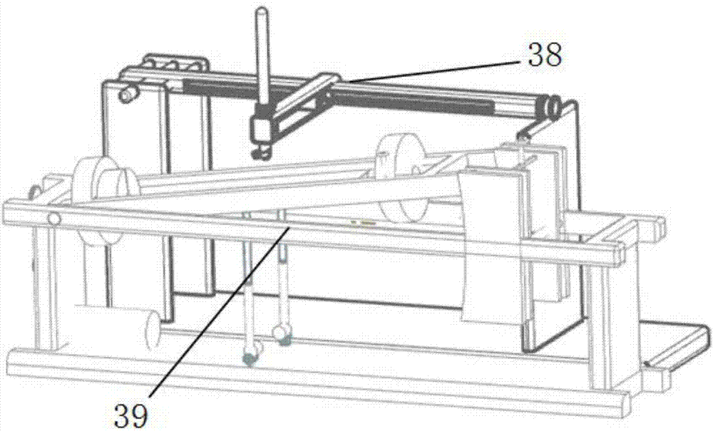
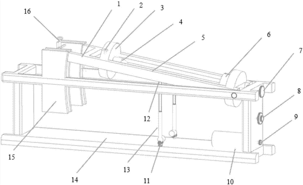
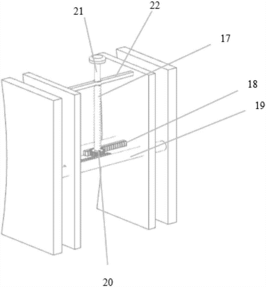
The invention discloses an engine crankshaft circular bead laser cladding repairing device and method solving the problem that in the prior art, crankshaft circular bead repairing is limited and having the beneficial effects of being convenient to operate and low in cost. According to the scheme of the engine crankshaft circular bead laser cladding repairing device and method, the engine crankshaft circular bead laser cladding repairing device comprises a crankshaft cladding clamp used for clamping a crankshaft and a three-axis driving mechanism arranged on one side of the clamp support; the crankshaft cladding clamp comprises a chuck used for driving the crankshaft to rotate around the axis of the crankshaft, the chuck is supported through a clamp support, and the crankshaft cladding clamp can ascend and descend so as to drive the crankshaft to incline in the set angle range; the three-axis driving mechanism comprises a supporting frame, the supporting frame supports a first sliding rail, the first sliding rail is provided with an X-direction guide rail capable of moving along the first sliding rail, the X-direction guide rail is provided with a Y-direction connecting rod capable of moving along the X-direction guide rail, the Y-direction connecting rod is provided with a Z-direction lead screw capable of moving up and down relative to the Y-direction connecting rod, and the Z-direction lead screw is fixed to a laser cladding head.

Description

technical field [0001] The invention relates to the field of laser cladding, in particular to a laser cladding repair device and method for engine crankshaft rounded corners. Background technique [0002] Crankshafts operate in a high-pressure, high-temperature working environment for a long time, and are often scrapped due to friction, scratches and cracks on the journal surface, resulting in huge waste of resources and economic losses, and most of the scrapped engine crankshafts contain high remanufacturing value. If it is repaired by laser cladding technology, the waste caused by scrapping the crankshaft can be reduced, and the performance of the crankshaft surface can also be improved. Laser cladding technology refers to placing selected coating materials on the surface of the coated substrate with different filler methods, melting it and the thin layer of the substrate surface at the same time through laser irradiation, and forming a very low dilution after rapid solid...

Claims


Application Information

Patent Timeline
Patent Type & Authority Applications(China)
IPC IPC(8): B23K26/00B23K26/08
CPCB23K26/0823B23K26/354
Inventor 李燕乐翟维东陈晓晓尹光磊孙杰李方义李剑峰
Owner SHANDONG UNIV
Learn More