Tail gas treatment system of high-temperature separation device of recycled cables
A separation device and tail gas treatment technology, which is applied in the direction of combination device, separation method, and dispersed particle separation, can solve the problems of waste gas recovery and impurity removal, and achieve the effect of efficient recovery and pollution avoidance
- Summary
- Abstract
- Description
- Claims
- Application Information
AI Technical Summary
Problems solved by technology
Method used
Image
Examples
Embodiment 1
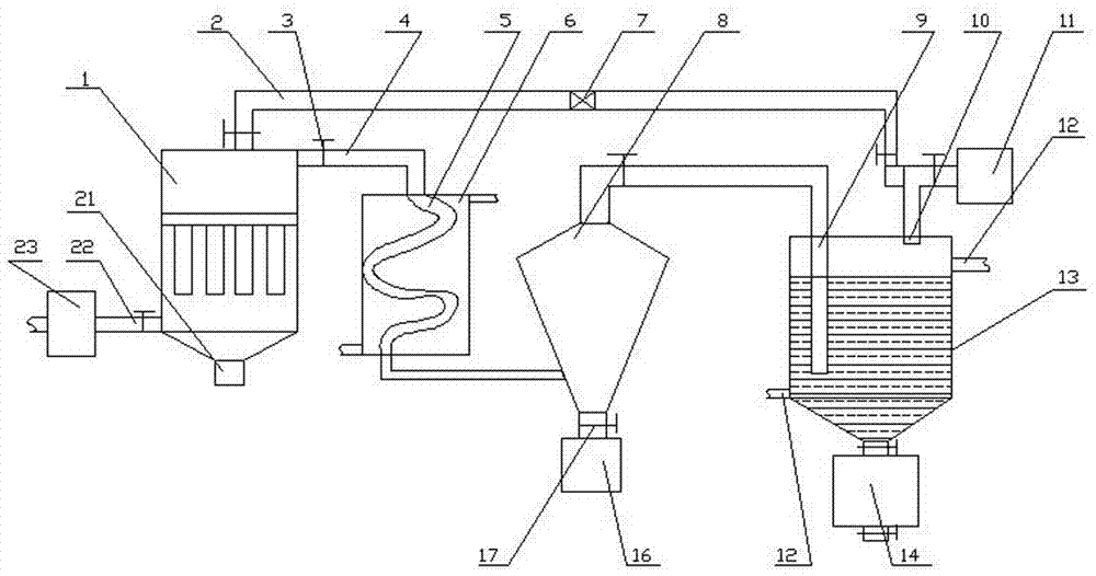
[0038] A recovery cable high temperature separation device tail gas treatment system, comprising a primary dust removal mechanism, a first dust removal mechanism connected to the primary dust removal mechanism, a transducer mechanism connected to the first end of the first dust removal mechanism, and the The first regeneration mechanism connected to the second end of the first dust removal mechanism, the settling mechanism connected to the energy conversion mechanism, the dust accumulation module arranged at the lower part of the settling mechanism, and the absorption mechanism arranged at the rear of the settling mechanism , the discharge mechanism 11 arranged on the upper part of the absorption mechanism, the circulation mechanism connected with the absorption mechanism, and the unloading module arranged at the lower part of the absorption mechanism;
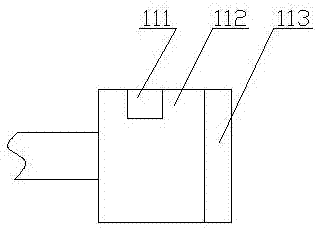
[0039] The primary dust removal mechanism 23 includes an air duct 231 connected to the high temperature separation device, a ...
Embodiment 2
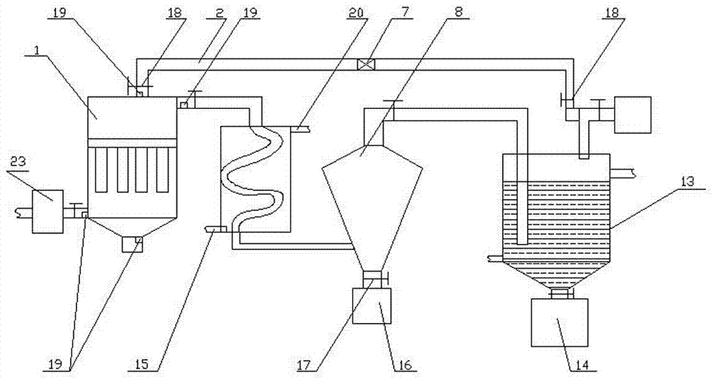
[0050] Embodiment 2, which is different from Embodiment 1 in that: the regeneration pipeline 2, the regeneration discharge pipe 21, and the first air intake pipe 22 are all equipped with a detection module 19;
[0051] The detection module 19 includes a flow rate sensor 192 , a dust sensor 191 and a temperature sensor 193 .
[0052] The dedusting liquid 240 is arranged in the dedusting compartment 232, and is connected with the circulation pool 238 for the circulation of the dedusting liquid with the side wall of the dedusting compartment 232, and the interval net 241 arranged in the circulation pool 238 is arranged in the circulation pool 238 The upper liquid inlet pipe 236 , the liquid discharge pipe 237 arranged on the bottom surface of the circulation pool 238 , and the water pump 234 arranged on the upper water pipe 235 between the dust removal compartment 232 and the circulation pool 238 .
[0053] The first regeneration mechanism adopted in this embodiment includes a re...
Embodiment 3
[0054] Embodiment 3: The difference between it and Embodiment 2 is that: the first dust removal mechanism, the energy conversion mechanism, the first regeneration mechanism, the sedimentation mechanism, the dust accumulation module, the absorption mechanism, the discharge mechanism, the circulation mechanism, and the unloading module are all compatible with The signal interconnection of the control modules arranged on the outer wall of the dust collector;
[0055] The control module is PLC or personal computer.
[0056]The settling mechanism adopted in this embodiment includes a conical cylinder whose lower part communicates with the spiral tube, and the air inlet pipe is arranged in the tangential direction of the side wall of the conical cylinder, so that the airflow entering it is a helical airflow, thereby generating a high-speed swirling airflow , and as the airflow rises, due to the increase in space, large particles settle and fall into the dust accumulation module, whi...
PUM
 Abstract
Description
Claims
Application Information
 - R&D
- Intellectual Property
- Life Sciences
- Materials
- Tech Scout
- Unparalleled Data Quality
- Higher Quality Content
- 60% Fewer Hallucinations
Browse by: Latest US Patents, China's latest patents, Technical Efficacy Thesaurus, Application Domain, Technology Topic, Popular Technical Reports.
© 2025 PatSnap. All rights reserved.Legal|Privacy policy|Modern Slavery Act Transparency Statement|Sitemap|About US| Contact US: help@patsnap.com


