
Portable numerical control cutting machine

A cutting machine and portable technology, applied in the field of portable CNC cutting machines, can solve the problems of non-cutting, difficult movement, low work efficiency, etc., and achieve the effects of reducing space occupation, ensuring work quality, and being convenient to carry

Inactive Publication Date: 2017-09-15
张艳
View PDF0 Cites 1 Cited by
  • Summary
  • Abstract
  • Description
  • Claims
  • Application Information

AI Technical Summary

Problems solved by technology

Before cutting the steel plate, the steel plate must be raised, and then the portable CNC cutting machine is placed on the steel plate for cutting. There are no regulations on the specification, quantity and placement of the pads supporting the steel plate, and they are placed randomly. The steel plate cannot be very flat after being raised, and the steel plate itself is not necessarily very flat, and the portable CNC cutting machine is supported by three points. When the cutting plane is not parallel to the steel plate plane, during the cutting process, the cutting nozzle and the steel plate The distance between them will change continuously. When cutting with flame, the parts will have problems such as cutting and cutting tumors that are difficult to clean or some parts are not cut through. At the same time, when changing the workplace, the plane size of the cutting machine is large, and it is difficult to move. However, if it is disassembled and moved, it needs to be reassembled. The main engine and the base, the beam and the main engine are rack and gear meshed. Frequent disassembly and installation will affect the meshing accuracy. Not only the work efficiency is low, but also the accuracy of the equipment and the blanking accuracy of the parts will be affected.

Method used


Image

  • Portable numerical control cutting machine
  • Portable numerical control cutting machine
  • Portable numerical control cutting machine

Examples


Embodiment Construction

[0016] The following will clearly and completely describe the technical solutions in the embodiments of the present invention with reference to the accompanying drawings in the embodiments of the present invention. Obviously, the described embodiments are only some, not all, embodiments of the present invention.

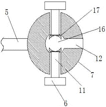
[0017] refer to Figure 1-3 , a portable numerical control cutting machine, comprising a cutting machine body 1, a base 2 is slidably connected to one side of the cutting machine body 1, a slider 3 is rotatably connected to the side of the cutting machine body 1 close to the base 2, and a slider 3 is provided on the base 2 There are four sets of limit slide bars 11 on the cutting machine body 1, and a chute to match the limit slide bars 11 on the base 2, and the limit slide bars 11 are far away from the base 2. A lifting plate 12 is vertically provided at one end of the cutting machine body 1. The lifting plate 12 is connected to the cutting machine body 1 by a sprin...


PUM


Abstract

The invention discloses a portable numerical control cutting machine, which comprises a cutting machine body, one side of the cutting machine body is slidably connected with a base, and the side of the cutting machine body close to the base is rotatably connected with a slider, and the base is provided with a There are through slots matching with the sliders, four sets of limit slide bars are provided on the cutting machine body, and chutes matching with the limit slide bars are provided on the base, and the limit slide bars are far away from the bottom of the base. One end is vertically provided with a lifting plate, and the lifting plate is connected to the cutting machine body through a spring. The cutting machine body is provided with a vertical beam, and one end of the beam is provided with a cutting torch. One side of the machine body is provided with two sets of rotating plates. The invention can keep the distance between the cutting torch and the steel plate uniform, and can avoid problems such as cutting tumors or incomplete cutting when cutting. At the same time, when changing the site, it does not need to be disassembled, and is easy to carry, ensuring the work quality.

Description

technical field [0001] The invention relates to the field of numerical control cutting machines, in particular to a portable numerical control cutting machine. Background technique [0002] In some special occasions, due to the limitations of raw material specifications and sites, it is necessary to use a portable CNC cutting machine for blanking operations. This cutting machine includes: main machine, base (longitudinal track), beam (horizontal track), cutting torch assembly, Below the base, there are three support blocks fixed, which are mainly used to support the base. Before cutting the steel plate, the steel plate must be raised, and then the portable CNC cutting machine is placed on the steel plate for cutting. There are no regulations on the specification, quantity and placement of the pads supporting the steel plate, and they are placed randomly. The steel plate cannot be very flat after being raised, and the steel plate itself is not necessarily very flat, and the ...

Claims


Application Information

Patent Timeline
Patent Type & Authority Applications(China)
IPC IPC(8): B23K7/00B23K7/10
CPCB23K7/00B23K7/10
Inventor 张艳
Owner 张艳
Learn More