Forward and reverse rotation control and implementation method of Magnus effect vertical-axis wind turbine rotor

An implementation method and technology of wind turbines, applied in the control of wind turbines, engine control, wind turbines, etc., can solve the problems of large mechanical loss, large moment of inertia of cylinders, and difficult commutation

Inactive Publication Date: 2017-09-12
苏州盛恒兴自动化设备有限公司
View PDF4 Cites 7 Cited by
  • Summary
  • Abstract
  • Description
  • Claims
  • Application Information

AI Technical Summary

Problems solved by technology

[0004] The wind power generation device has not achieved the effect of large-scale power generation because of its mechanical complexity: in order to make the lift generated on the cylindrical rotor drive the trolley to reciprocate on the circular track, the rotating cylinder must move between the arcs of each upwind port and the bottom. Change the rotation direction once at the joint point of the tuyere arc; in order to obtain a large lift, the diameter and rotation speed of the cylinder are required to take large values, resulting in a large moment of inertia of the cylinder. Under the technical conditions at that time, changing the rotation speed and rotation speed of the rotor cylinder Steering can only be achieved with the help of complex mechanical systems, resulting in excessive mechanical losses
Also due to the difficulty of reversing and the limitations of manufacturing and control technology, the rotational speed of the cylinder is too low, so that its aerodynamic characteristics cannot be fully utilized, and the frictional resistance loss of the car body track makes the operating efficiency of this type of wind turbine far inferior to the level Shaft wind turbines are high and are eventually abandoned

Method used


Image

  • Forward and reverse rotation control and implementation method of Magnus effect vertical-axis wind turbine rotor
  • Forward and reverse rotation control and implementation method of Magnus effect vertical-axis wind turbine rotor
  • Forward and reverse rotation control and implementation method of Magnus effect vertical-axis wind turbine rotor

Examples


Embodiment Construction

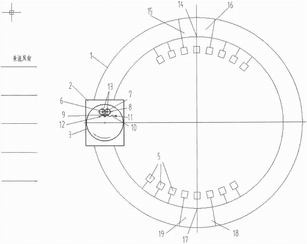
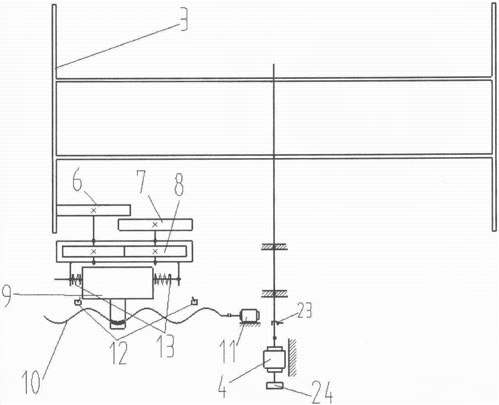
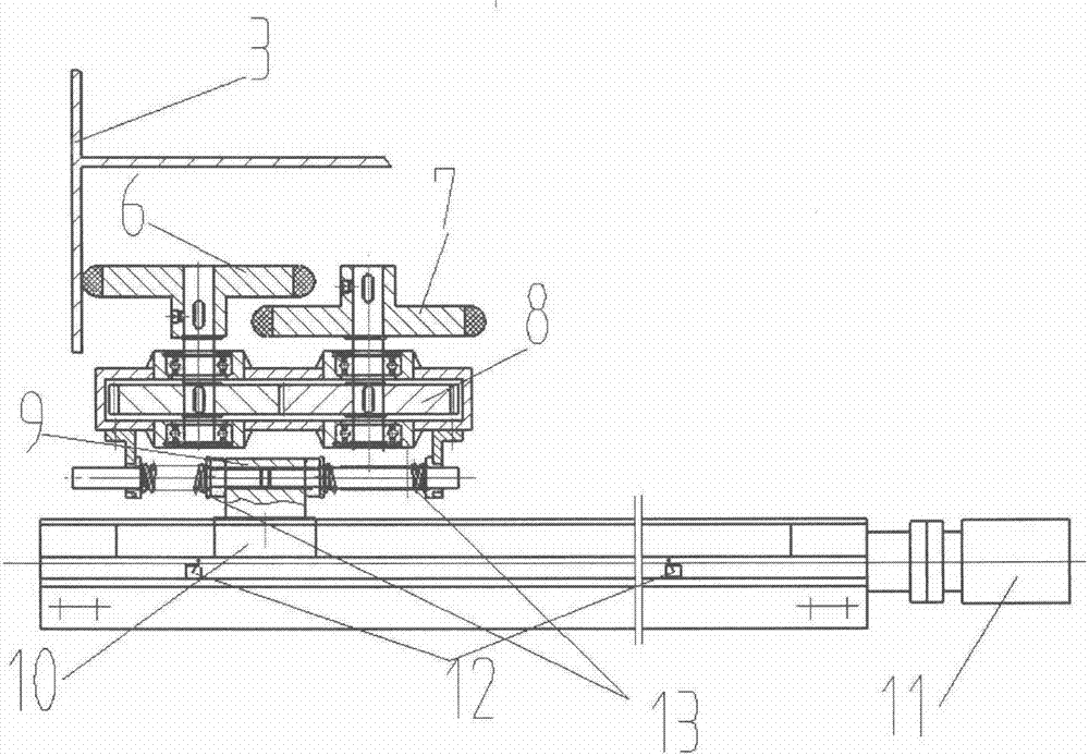
[0038] In the embodiment of the present invention, a Magnus effect vertical axis wind turbine rotor forward and reverse control and implementation method is provided. According to the on-site wind direction, the orientation of the forward and reverse conversion point of the wind turbine rotor is adjusted in real time, and at the conversion point The dynamic reversing area of ​​the rotor is set before and after the rotor. Through the energy storage mechanism with two buffer wheels with opposite rotation directions, part of the energy of the forward rotation of the rotor can be stored and converted into the starting energy after the rotor reverses. The frequency conversion control motor is fully Using the period of time when the rotor passes through the commutation zone, gradually increase the driving frequency of the motor to a predetermined value based on the starting speed of the rotor inversion and the dynamic characteristics of the system, and reduce the energy consumption in...


PUM


Abstract

The invention relates to a forward and reverse rotation control and implementation method of a Magnus effect vertical-axis wind turbine rotor. The method comprises a circular rail, a rail car, a cylindrical rotor, a rotor motor, a variable frequency speed adjuster, a speed sensor, a brake, buffer wheel energy storage mechanism, a buffer wheel displacement motor, a wind power sensor, a main controller, rotor direction identifiers and the like. The direction identifiers are arranged in such 36 areas as the circular rail; according to wind power signals, a reversing area of the cylindrical rotor on the rail is set online; after the rotor enters the reversing area, the displacement drives one buffer wheel to contact with the rotor; the rotating energy of the rotor is absorbed; then, the rotor is braked; the other buffer wheel reversely rotated is contacted with the rotor to reversely return the energy to the rotor; and the controller gradually improves the driving frequency through the variable frequency speed adjuster in the reversing area according to reverse rotation initial rotating speed obtained by the rotor, so that the rotor obtains reasonable acceleration to achieve the purpose of reducing the energy consumption in rotor steering.

Description

technical field [0001] The invention relates to the field of vertical-axis wind turbines, in particular to a forward and reverse control method of a Magnus effect vertical-axis wind turbine rotor. Background technique [0002] For a long time, because the wind energy utilization rate of vertical axis wind turbines is not as high as that of horizontal axis wind turbines, its development has been limited. However, horizontal axis wind turbines have high costs in manufacturing, installation and maintenance, and relatively strict requirements on wind field conditions The impact on the ecological environment such as the survival of birds has gradually become prominent, and the research and application of vertical axis wind turbines have received renewed attention. [0003] The Madaras rotor vertical axis wind test machine is a large-scale experimental scheme conceived and built by American engineer Julius D. Madaras in 1933 (for a 40MW wind field). Its rotor design principle is b...

Claims


Application Information

Patent Timeline
Patent Type & Authority Applications(China)
IPC IPC(8): F03D7/06
CPCF03D7/06F05B2270/321F05B2270/81Y02E10/74
Inventor 李超
Owner 苏州盛恒兴自动化设备有限公司
Why Eureka
Try Eureka