Eureka AIR delivers breakthrough ideas for toughest innovation challenges, trusted by R&D personnel around the world.

Detonation-wave-front high-voltage electric plasma gas relay coupling ignition detonation engine

A detonation engine and plasma gas technology, applied in the field of aviation power, can solve problems such as huge noise, unstable thrust, strong vibration, etc., and achieve good market prospects

Active Publication Date: 2017-09-08
江苏知聚知识产权服务有限公司
View PDF5 Cites 2 Cited by
  • Summary
  • Abstract
  • Description
  • Claims
  • Application Information

AI Technical Summary

Problems solved by technology

In addition, PDE also needs to design fast-acting, propulsion valves and fuel valves with flight weight and control system components, as well as advanced combustion control systems, effective inlets and nozzles, and comprehensive design solutions for special parts of the system; 4) due to the lack of thrust Stable, practical PDE needs to adopt a multi-tube structure with high frequency (greater than 80 Hz), and there is a problem of dynamic coupling between multi-tube detonation combustion chambers; 5) Cooling problem: the speed of hot gas after the detonation wave is extremely high, causing The heat of the tube wall increases, so efficient cooling measures must be taken; 6) Accurate theoretical analysis of the knock phenomenon; 7) Strong vibration and loud noise will be generated during knock combustion

Method used


Image

  • Detonation-wave-front high-voltage electric plasma gas relay coupling ignition detonation engine
  • Detonation-wave-front high-voltage electric plasma gas relay coupling ignition detonation engine

Examples


Embodiment Construction

[0016] Attached below figure 1 And embodiment further illustrate the present invention.

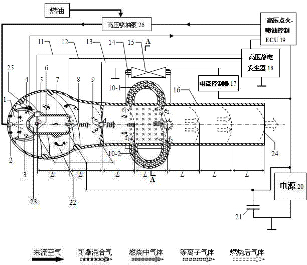
[0017] The present invention consists of a pre-mixing indoor spiral guide bar (4), a pre-detonation combustion tube outer spiral guide bar (5), a high-pressure ignition head b (6), a pre-detonation combustion tube (7), a high-pressure ignition head c (8) , high-voltage ignition head d (9), upper plasma guide tube (10-1), lower plasma guide tube (10-2), ignition head b high-voltage ignition wire (11), ignition head c high-voltage ignition wire (12) , ignition head c high-voltage ignition wire (13), toroidal magnetic pole plate (14), magnetic field coil (15), detonation nozzle (16), current controller (17), high-voltage ignition-fuel injection control ECU (19) , fuel air premix chamber (22), pre-detonation combustion tube air inlet (23), wind speed sensor (25), high-pressure fuel injection pump (26);

[0018] The technical solution adopted in the present invention is: an air inlet (1) is ...


PUM


Abstract

The invention relates to a detonation-wave-front high-voltage electric plasma gas relay coupling ignition detonation engine which is formed by a pre-detonation burning pipe (7), a high-voltage ignition head c (8), a high-voltage ignition head, a plasma flow guide pipe (10), an annular face magnetic pole plate (14), a field coil (15), a detonation spraying pipe (16), a current controller (17), a high-voltage ignition-oil injection control ECU (19), a fuel and air premixing chamber (22), an air velocity transducer (25) and a high pressure oil spraying pump (26). Through multi-stage high-voltage ignition and plasma gas discharge, after a tiny pulse detonation wave is subject to three-stage relay coupling ignition, energy is amplified continuously, the best energy is achieved finally, the energy is sprayed out from a fuel gas spraying opening (24), and generation of detonation is guaranteed. The detonation-wave-front high-voltage electric plasma gas relay coupling ignition detonation engine has the beneficial effects that (1) the detonation, control and quick holding of the knock can be solved, and the pulse detonation wave can be gradually amplified; (2) atomization, jetting and doping of liquid fuel and an oxidizing agent can be achieved; (3) stable pushing force can be generated, low frequency to high-frequency continuous work can be achieved; and (4) pulse knock engine power adjustment can be achieved.

Description

technical field [0001] The invention relates to a power machine, in particular to a high-voltage electric plasma gas-relay coupled ignition detonation engine before a detonation wave, and belongs to the technical field of aviation power. Background technique [0002] The pulse detonation engine (PDE) directly uses the detonation wave generated by detonation combustion in the combustion chamber to compress the gas, and then generate power. Compared with the traditional engine, the pulse detonation engine saves the compressor, turbine and other components, and has the characteristics of simple structure, high thrust-to-weight ratio, and low cost. In the future, whether rockets, missiles, or aerospace aircraft can use pulse detonation engines, it is also considered to be the most potential aerospace power project in the 21st century. [0003] PDE has simple structure (no rotating parts such as turbine), small size (no more than 2 meters), wide application range, low cost, can ...

Claims


Application Information

Patent Timeline
Patent Type & Authority Applications(China)
IPC IPC(8): F02K7/075F02K1/78
CPCF02K1/78F02K7/075
Inventor 陈蜀乔
Owner 江苏知聚知识产权服务有限公司
Why Eureka
Eureka Blog
Learn More