Optical system of surgery microscope
A technology of surgical microscope and optical system, applied in microscopes, optics, optical components, etc., can solve problems such as prolonging operation time
- Summary
- Abstract
- Description
- Claims
- Application Information
AI Technical Summary
Problems solved by technology
Method used
Image


Examples
Embodiment 1
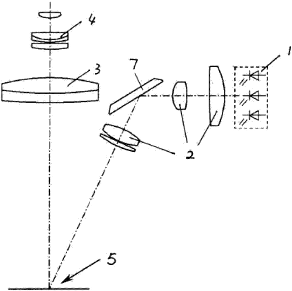
[0031] Such as figure 1 As shown, an optical system of an operating microscope includes a light source 1, an illumination optical system and a microscopic optical system. The microscopic optical system magnifies the observed object through multiple groups of optical elements, which includes a large objective lens group 3, a variable magnification lens group 4, and the like.
[0032] Its light source 1 adopts a high-power white light emitting diode. When designing, several light-emitting diodes can be arranged to form a light-emitting diode array. For different working light output needs, it can be realized by increasing or decreasing the number of light-emitting diodes, changing their arrangement density and arrangement method.
[0033] The illumination optical system of the optical system is a group of optical elements, which are structurally independent from the microscopic optical system and provide illumination. A first condenser lens group 2, a reflector 7, and a secon...
Embodiment 2
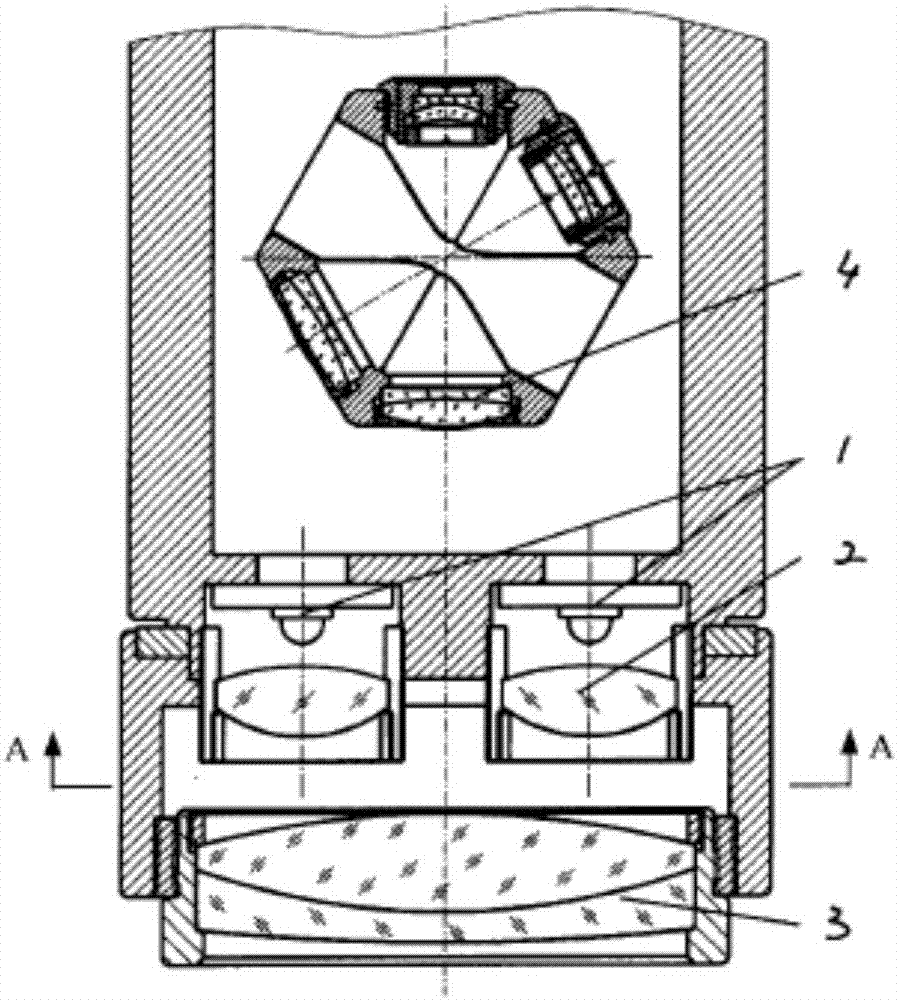
[0036] Such as figure 2 , image 3 As shown, in this embodiment, the light source and the micro-optical system are more closely designed together. The light source of the optical system of the surgical microscope is composed of a pair of illuminants 1, and the illuminant 1 can be a high-power white light-emitting diode. If a higher brightness light output is required, the light-emitting diodes can also be formed into a matrix light source instead of a single light-emitting diode. Diodes are used. The two illuminants are arranged symmetrically on both sides of the main light path of the micro-optical system. In the projection direction of the main optical path of the microscopic optical system, the connection line of the pair of illuminants is perpendicular to the connection line of the binoculars of the variable magnification lens group. This is in order to prevent the setting of illuminant 1 from blocking the use of variable power lens group 4 (its eyeglasses are binocula...
Embodiment 3
[0039] The difference from Example 2 is that, as Figure 4 As shown, there are a pair of hole missing parts 6 on the large objective lens group 3 . The light emitting diode 1 and its condenser lens group 2 are arranged directly above the hole missing part 6 , the light emitted by the light emitting diode 1 is converged by the condenser lens group 2 , passes through the hole missing part 6 of the large objective lens group 3 , and reaches the working area 5 .
[0040] Of course, for the above two embodiments, the use of a pair of illuminants is not limited, and only one illuminant can be used if the illumination meets the requirements; or the volume of the illuminant is small enough to not block the use of other optical components In some cases, a larger number of illuminants can be set.
[0041] In addition, there are other technical solutions, such as Figure 5 As shown, the light emitting diode 1 and its condenser lens group 2 can be arranged under or around the large obje...
PUM
 Abstract
Description
Claims
Application Information
 - R&D
- Intellectual Property
- Life Sciences
- Materials
- Tech Scout
- Unparalleled Data Quality
- Higher Quality Content
- 60% Fewer Hallucinations
Browse by: Latest US Patents, China's latest patents, Technical Efficacy Thesaurus, Application Domain, Technology Topic, Popular Technical Reports.
© 2025 PatSnap. All rights reserved.Legal|Privacy policy|Modern Slavery Act Transparency Statement|Sitemap|About US| Contact US: help@patsnap.com