V-method mold casting technique for casting complicated pedestal of home appliance mold
A home appliance mold and casting process technology, which is applied to casting molding equipment, casting molds, and casting mold components. Good casting quality and sand mold quality
- Summary
- Abstract
- Description
- Claims
- Application Information
AI Technical Summary
Problems solved by technology
Method used
Image


Examples
Embodiment 1
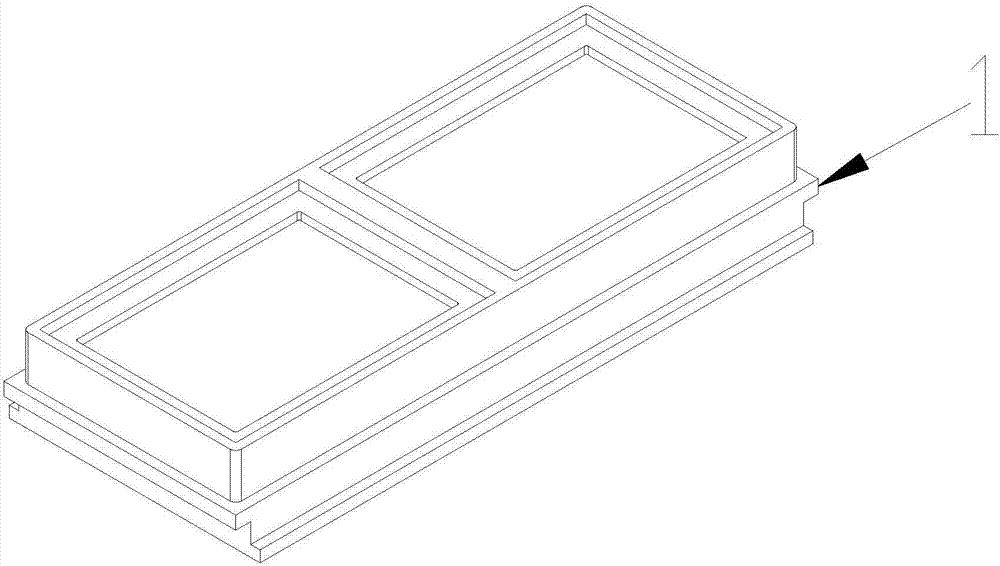
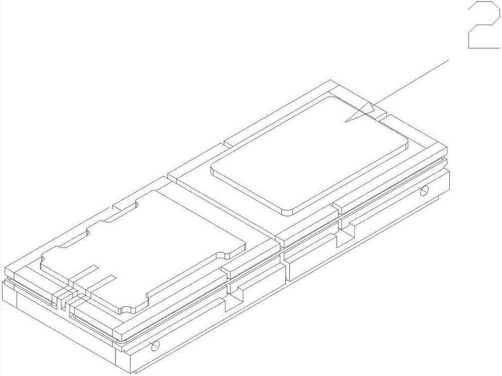
[0042] 1. Use 3D software to perform parting operation on the 3D base. The parting surface is selected as the bottom surface. The separated models are the lower die model 1 and the upper die model 2. The upper die model 2 is the inner shape, but in order to Therefore, the upper die model 2 should be made into a convex shape with the parting surface as the zero point, so that the lower die model 1 and the upper die model 2 are all convex ( Figure 1-3 shown).
[0043] 2. Optimize the upper mold model 2 again. First, make a rectangle with the maximum length and width of the upper mold model 2, and then expand the four sides of the rectangle by 20mm. The height is the highest point at the bottom of the top boss, and make a cuboid. The top boss and the cuboid are fused to obtain the upper mold model block 3 ( Figure 4 shown).
[0044] 3. Then perform Boolean operations on the above-mentioned cuboid and the upper mold model 2, you can wait for a back-shaped entity, divide the ba...
Embodiment 2
[0051] 1. Use 3D software to perform parting operation on the 3D base. The parting surface is selected as the bottom surface. The separated models are the lower die model 1 and the upper die model 2. The upper die model 2 is the inner shape, but in order to Therefore, the upper die model 2 should be made into a convex shape with the parting surface as the zero point, so that the lower die model 1 and the upper die model 2 are all convex ( Figure 1-3 shown).
[0052] 2. Optimize the upper mold model 2 again. First, make a rectangle with the maximum length and width of the upper mold model 2, and then expand the four sides of the rectangle by 30mm. The height is the highest point at the bottom of the top boss, and make a cuboid. The top boss and the cuboid are fused to obtain the upper mold model block 3 ( Figure 4 shown).
[0053] 3. Then perform Boolean operations on the above-mentioned cuboid and the upper mold model 2, you can wait for a back-shaped entity, divide the ba...
Embodiment 3
[0061] 1. Use 3D software to perform parting operation on the 3D base. The parting surface is selected as the bottom surface. The separated models are the lower die model 1 and the upper die model 2. The upper die model 2 is the inner shape, but in order to Therefore, the upper die model 2 should be made into a convex shape with the parting surface as the zero point, so that the lower die model 1 and the upper die model 2 are all convex ( Figure 1-3 shown).
[0062] 2. Optimize the upper mold model 2 again. First, make a rectangle with the maximum length and width of the upper mold model 2, and then expand the four sides of the rectangle by 25mm. The height is the highest point at the bottom of the top boss, and make a cuboid. The top boss and the cuboid are fused to obtain the upper mold model block 3 ( Figure 4 shown).
[0063] 3. Then perform Boolean operations on the above-mentioned cuboid and the upper mold model 2, you can wait for a back-shaped entity, divide the ba...
PUM
| Property | Measurement | Unit |
|---|---|---|
| diameter | aaaaa | aaaaa |
| density | aaaaa | aaaaa |
Abstract
Description
Claims
Application Information
 - Generate Ideas
- Intellectual Property
- Life Sciences
- Materials
- Tech Scout
- Unparalleled Data Quality
- Higher Quality Content
- 60% Fewer Hallucinations
Browse by: Latest US Patents, China's latest patents, Technical Efficacy Thesaurus, Application Domain, Technology Topic, Popular Technical Reports.
© 2025 PatSnap. All rights reserved.Legal|Privacy policy|Modern Slavery Act Transparency Statement|Sitemap|About US| Contact US: help@patsnap.com