
Microfracture instrument

a micro-fracture and instrument technology, applied in the field of surgical instruments, can solve the problems of unsuitable manual instruments, insufficient accessibility or visibility of site sites, picks to slide or gouge targets, etc., and achieve the effect of quick placement of micro-fractures, less time, and quick drilling of small diameter holes

Active Publication Date: 2014-10-07
ARTHREX
View PDF21 Cites 61 Cited by
  • Summary
  • Abstract
  • Description
  • Claims
  • Application Information

AI Technical Summary

Benefits of technology

The present invention is about an instrument that can quickly and accurately create small fractures in bones at specific angles. This instrument is attached to a power system and is much faster and easier to use than previous methods. It has a flexible tip and a curved outer sheath that protects it during insertion and is retracted once positioned. With this instrument, surgeons can easily and quickly place microfractures in the desired position with only one tool.

Problems solved by technology

The manual instruments are undesirable in that they typically require two hands to use since a mallet is used to drive the instruments into the bone.
In addition, the impact loading of the mallet may cause the pick to slide or gouge the target site rather than puncture the site perpendicular to the axis of the trocar tip.
The straight drill power instrument does not provide adequate accessibility or visibility to the site which is typically in a joint space.

Method used


Image

  • Microfracture instrument
  • Microfracture instrument
  • Microfracture instrument

Examples


Embodiment Construction

[0026]The following description is provided to enable any person skilled in the art to make and use the invention and sets forth the best modes contemplated by the inventors of carrying out their invention. Various modifications, however, will remain readily apparent to those skilled in the art.

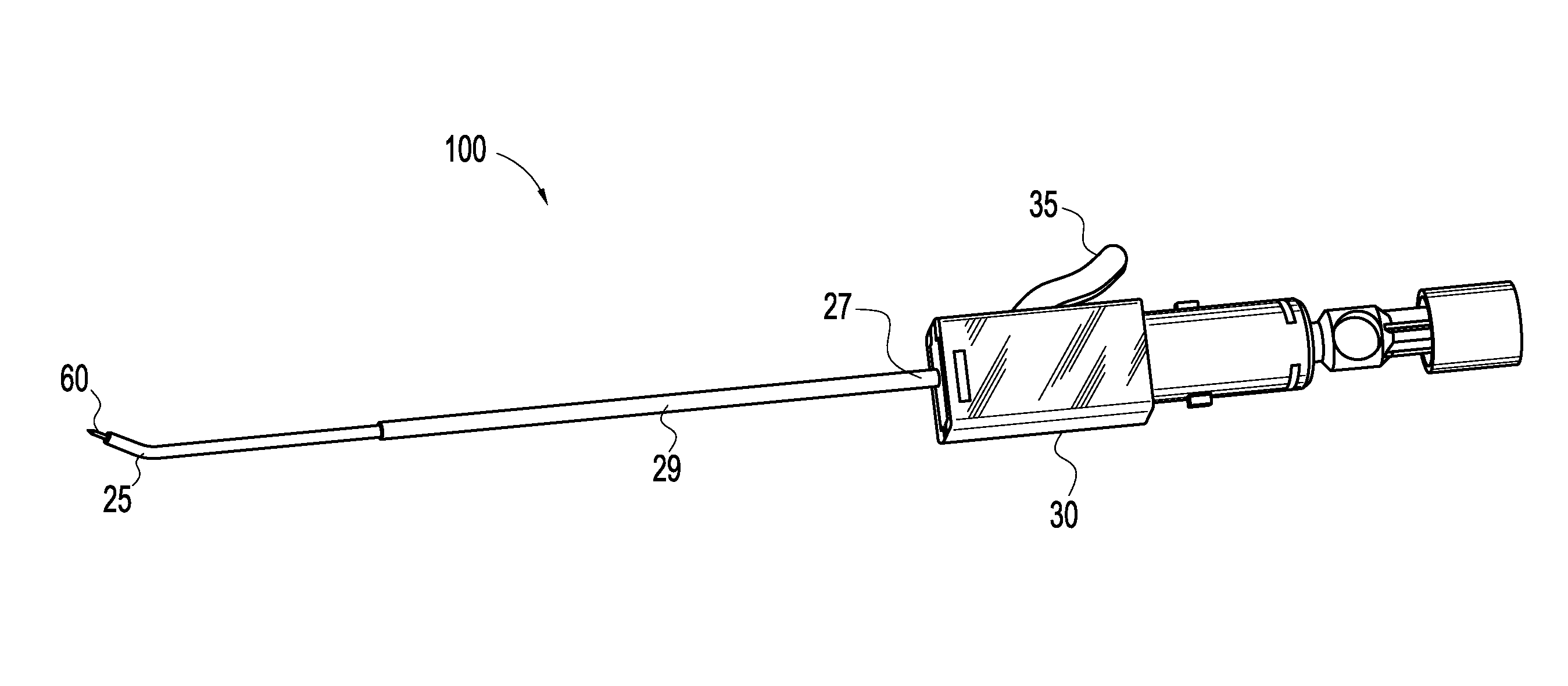
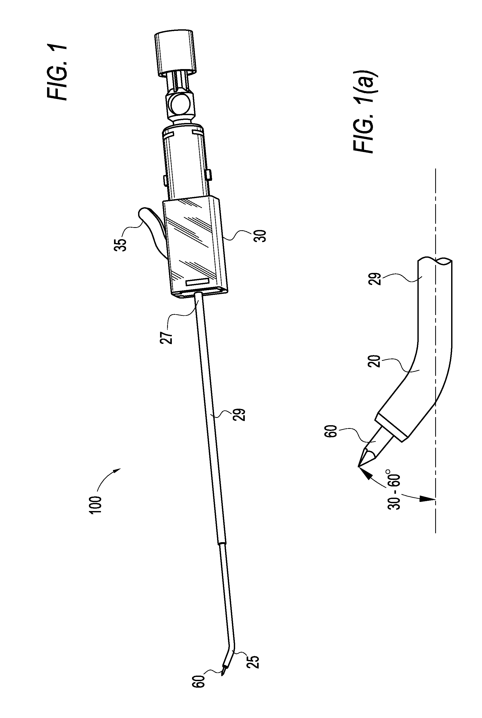
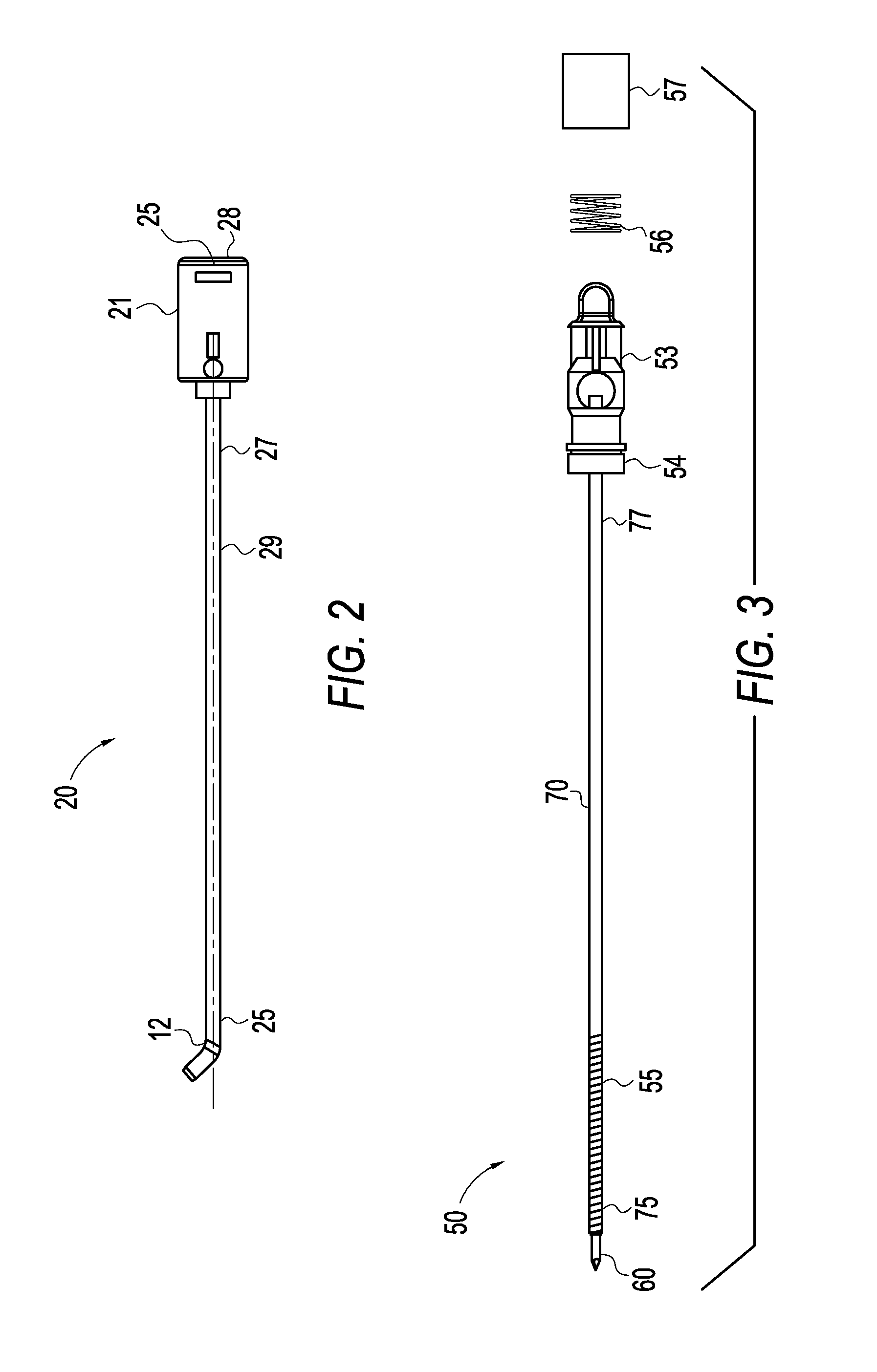
[0027]The present invention provides a microfracture instrument for forming small diameter holes in bone. The microfracture instrument of the present invention is designed to attach to a power system (such as one used for shavers and burrs, for example) to quickly drill small diameter holes at pre-determined angles into bone. The microfracture instrument is provided with a flexible trocar tip and a curved outer sheath. The shaft of the flexible trocar tip connects to the hand piece. The outer sheath protects the sharp trocar tip during insertion and is retracted once positioned to expose the sharp trocar tip. The instrument allows the surgeon to quickly place the microfractures at the desired...


PUM


Abstract

A bone drill that includes a shaft with a flexible portion having a proximal end and a distal end and a drill tip coupled to the distal end of the shaft. The bone drill also includes a cannulated sheath with a proximal end and a distal end, the sheath housing a portion of the shaft and having a curved portion at the distal end. The drill tip may also be housed within the curved portion of the sheath. The bone drill may also include a hub with an actuator mechanism, the hub being coupled to the sheath, wherein the actuator mechanism retracts the sheath to cause the drill tip to extend beyond the distal end of the sheath.

Description

CROSS-REFERENCE TO RELATED APPLICATIONS[0001]This application claims the benefit of U.S. Provisional Application No. 61 / 164,732, filed Mar. 30, 2009, the entire disclosure of which is incorporated by reference herein.FIELD OF THE INVENTION[0002]The present invention is directed to surgical instruments and, more particularly, to a device for treating chondral defects of the knee.BACKGROUND OF THE INVENTION[0003]Treatment of articular cartilage defects is typically accomplished by the microfracture procedure. This procedure is performed arthroscopically. Although articular cartilage defects may occur in any joint, the microfracture procedure is typically performed in the knee or shoulder. The surgeon visually assesses the defect and performs the procedure using special instruments that are inserted through small incisions around the joint. Unstable and loose cartilage is removed from the exposed bone so that there is a stable edge of cartilage surrounding the defect. Multiple holes (a...

Claims


Application Information

Patent Timeline
Patent Type & Authority Patents(United States)
IPC IPC(8): A61B17/16A61B17/17A61B17/32
CPCA61B17/1633A61B17/1675A61B17/1604A61B17/1631A61B17/1642A61B17/32002A61B2017/320032
Inventor SCHMIEDING, REINHOLDADAMS, KENNETH M.O'QUINN, PHILIP S.MILLETT, PETER J.
Owner ARTHREX
Learn More