
A water pollution treatment device based on a GSM network

A technology of GSM network and treatment equipment, which is applied in the direction of heating water/sewage treatment, multi-stage water/sewage treatment, water/sludge/sewage treatment, etc. It can solve the real-time monitoring of wastewater, affect the effect of water quality treatment, and do not consider linkage control And other issues

Inactive Publication Date: 2017-08-15
GUANGXI NANNING DETONG NETWORK
View PDF0 Cites 0 Cited by
  • Summary
  • Abstract
  • Description
  • Claims
  • Application Information

AI Technical Summary

Problems solved by technology

The traditional biochemical treatment system does not consider linkage control and water quality monitoring, and there is a situation where the fan runs for a long time regardless of water quality changes, that is, although the inflow of water has stopped or its organic matter has been decomposed by microorganisms, because there is no continuous real-time monitoring of wastewater, As a result, the fan runs continuously, resulting in energy waste, or although there is water inflow, the content of organic matter in the water is also different, the activities of microorganisms are also in different stages, and the demand for oxygen is also different, so the oxygen supply equipment is required to provide different amounts of oxygen. The fan cannot be adjusted in a timely manner, which affects the effect of water quality treatment. In addition, the existing sewage treatment equipment is small and cannot treat a large amount of sewage. In some small sewage treatment plants or enterprises that need to deal with water pollution, Small sewage treatment equipment cannot meet the demand for sewage treatment. Therefore, it is necessary to design a water pollution treatment equipment that can increase the treatment capacity

Method used


Image

  • A water pollution treatment device based on a GSM network

Examples


Embodiment Construction

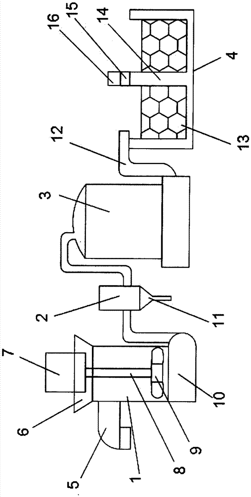
[0016] Such as figure 1 As shown, a water pollution treatment equipment based on the GSM network includes a flocculant mixer 1, a dosing device 2, an ammonia nitrogen removal tank 3 and a percolation recovery tank 4, and the left side of the flocculant mixer 1 is provided with a feed pipe 5. A top frame 6 is arranged above the flocculant mixer 1, a motor 7 is arranged on the top frame 6, a rotating shaft 8 and a stirring blade 9 are arranged below the motor 7, and the lower end of the flocculant mixer 1 is set There is a base 10, and the base 10 is connected to the dosing device 2, and the dosing device 2 is arranged between the flocculant mixer 1 and the ammonia nitrogen removal tank 3, and the lower end of the dosing device 2 is provided with a feeding pipe 11, the The right side of the ammonia nitrogen removal tank 3 is provided with a water delivery pipe 12, the water delivery pipe 12 is connected to the percolation recovery tank 4, and the percolation recovery tank 4 is l...


PUM


Abstract

The invention discloses water pollution treatment equipment based on GSM network, which includes a flocculant mixer, a dosing device, an ammonia nitrogen removal tank and a percolation recovery tank. A feed pipe is arranged on the left side of the flocculant mixer, and the flocculant A top frame is provided above the mixer, a motor is provided on the top frame, a rotating shaft and a stirring blade are provided below the motor, a base is provided at the lower end of the flocculant mixer, and the base is connected to a dosing device. The drug device is set between the flocculant mixer and the ammonia nitrogen removal tank, the lower end of the drug doser is provided with a feeding pipe, and the right side of the ammonia nitrogen removal tank is provided with a water delivery pipe, and the water delivery pipe is connected to the percolation recovery tank. The percolation recovery tank is located on the right side of the ammonia nitrogen removal tank, and the percolation body and the partition wall are arranged in the percolation recovery tank, and the gas concentration detector and the GSM module are arranged on the partition wall; the water pollution treatment equipment has a network The advantages of detection, simple structure, large processing capacity and low cost.

Description

technical field [0001] The invention relates to a water pollution treatment device based on a GSM network. Background technique [0002] With the development of local economy, the problem of non-point source water pollution caused by large-scale agriculture and modern livestock and poultry breeding wastewater has become increasingly serious. Key factor. Therefore, controlling non-point source water pollution from large-scale agriculture, animal husbandry, and fishery in rural areas has become one of the important measures to solve the problems of water quality deterioration in river basins and eutrophication of lakes, and is of great significance to the improvement of regional ecological environment. The domestic agricultural and livestock non-point source water pollution treatment technology is still in its infancy, and there are many deficiencies. Although some companies are improving these equipment to a certain extent, none of them are suitable for the actual condition...

Claims


Application Information

Patent Timeline
Patent Type & Authority Applications(China)
IPC IPC(8): C02F9/04C02F9/10G08C17/02C02F101/16
CPCC02F9/00C02F1/001C02F1/04C02F1/52C02F2101/16G08C17/02
Inventor 于建峰白克华黄丽琼
Owner GUANGXI NANNING DETONG NETWORK
Learn More