Rotary furnace capable of simultaneously adopting hydrogen forward and reverse supply

A rotary furnace and hydrogen technology, applied in the field of reduction furnaces, can solve the problems of difficult to control the oxygen content of tungsten powder, narrow particle size composition distribution range, large particle size distribution range, etc., achieve uniform particle size composition distribution range, narrow particle size composition distribution range, The effect of large particle size distribution

Active Publication Date: 2017-08-11
赣州鼎盛炉业有限公司
View PDF7 Cites 2 Cited by
  • Summary
  • Abstract
  • Description
  • Claims
  • Application Information

AI Technical Summary

Problems solved by technology

Both single cis-hydrogen reduction and single reverse hydrogen reduction have their own advantages and disadvantages. For example, the cis-hydrogen reduction speed is fast, the output is increased, the particle size composition distribution range is narrow and uniform, and the hydrogen flow rate is reduced by more than 1 / 3. The disadvantage is that cold hydrogen and cold material enter The heating zone consumes a lot of energy. After the reaction, the hydrogen gas and the tungsten powder are discharged in the same direction, and it is difficult to cool the tungsten powder. In addition, the moisture in the hydrogen gas increases, and the oxygen content in the tungsten powder is difficult to control; Cooling, hydrogen temperature rises, drying hydrogen is beneficial to oxygen content control, and discharging hydrogen can preheat WO3 entering the furnace tube
The disadvantage is that the WO3 entering the heating zone is in contact with the hydrogen gas with a large water content, and the reaction speed is slow; the hydrogen consumption is large and the energy is taken away, and the particle size distribution range is large and uneven; although the existing two-way adjustable reduction furnace has a certain application flexibility, but it is still simple to complete the cis-hydrogen reduction and anti-hydrogen reduction alternately in the same furnace, and the effect is not satisfactory

Method used


Image

  • Rotary furnace capable of simultaneously adopting hydrogen forward and reverse supply
  • Rotary furnace capable of simultaneously adopting hydrogen forward and reverse supply
  • Rotary furnace capable of simultaneously adopting hydrogen forward and reverse supply

Examples


Embodiment 1

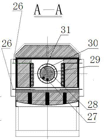
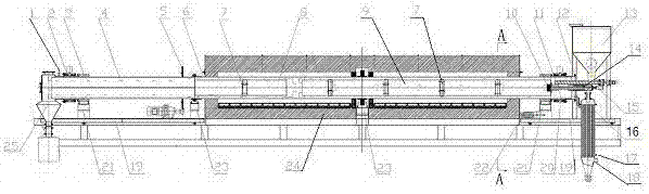
[0031] figure 1Middle: a rotary furnace that simultaneously supplies hydrogen in forward and reverse directions, including a furnace body 24 and a furnace tube 6, the furnace tube 6 passes through the furnace body 24 and is installed on the frame, and the furnace tube 6 is divided into a forward hydrogen reduction part and a reverse hydrogen reduction part; Wherein the cis-hydrogen reduction part includes a front inner furnace tube 9, a premixing chamber 20, and a heat exchanger 16. The front inner furnace tube 9 is connected and installed in the furnace tube 6 by a radial support 28, and the front inner furnace tube 9 and the furnace tube 6 are connected. A cis-hydrogen reduction zone is formed, a premixing chamber 20 is formed between the head of the front inner furnace tube 9 and the head of the furnace tube 6, and the head of the front inner furnace tube 9 is provided with an exhaust pipe 14 passing through the premixing chamber 20 to connect to the heat exchanger The hot ...

Embodiment 2

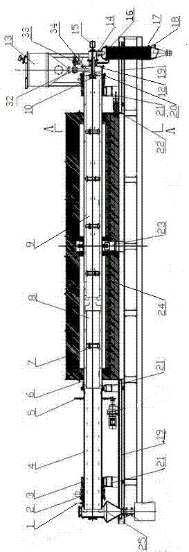
[0033] image 3 Middle: a rotary furnace that simultaneously supplies hydrogen in forward and reverse directions, including a furnace body 24 and a furnace tube 6, the furnace tube 6 passes through the furnace body 24 and is installed on the frame, and the furnace tube 6 is divided into a forward hydrogen reduction part and a reverse hydrogen reduction part; Wherein the cis-hydrogen reduction part includes a front inner furnace tube 9, a premixing chamber 20, and a heat exchanger 16. The front inner furnace tube 9 is connected and installed in the furnace tube 6 by a radial support 28, and the front inner furnace tube 9 and the furnace tube 6 are connected. A cis-hydrogen reduction zone is formed, a premixing chamber 20 is formed between the head of the front inner furnace tube 9 and the head of the furnace tube 6, and the head of the front inner furnace tube 9 is provided with an exhaust pipe 14 passing through the premixing chamber 20 to connect to the heat exchanger The hot...


PUM


Abstract

The invention discloses a rotary furnace capable of simultaneously adopting hydrogen forward and reverse supply, and relates to a reduction furnace. Through structural improvement of an inner pipe of the furnace, product quality can be controlled, and a large amount of hydrogen and energy can be saved; the furnace comprises a furnace body and a furnace pipe; the furnace pipe penetrates the furnace body to be mounted on a rack, and the furnace is characterized in that the furnace pipe is arranged to be high in front and low in rear, the furnace pipe comprises the forward hydrogen reduction portion and a reverse hydrogen reduction portion, the forward hydrogen reduction portion comprises a front inner furnace pipe and a pre-mixing chamber, the front inner furnace pipe is mounted in the furnace pipe axially, a forward hydrogen reduction area is formed between the front inner furnace pipe and the furnace pipe, a hydrogen inlet is formed in the head of the furnace pipe, an exhaust pipe is arranged on the head of the front inner furnace pipe and penetrates the pre-mixing chamber to purify returned hydrogen, the reverse hydrogen reduction portion comprises a discharging pipe and a rear inner furnace pipe, the rear inner furnace pipe is axially mounted in the furnace pipe, the front end of the rear inner furnace pipe is closed, a certain distance is arranged between the front end of the rear inner furnace pipe and the rear end of the front inner furnace pipe, the rear end of the rear inner furnace pipe is close to the discharging pipe, and the tail end of the discharging furnace pipe is provided with a cold hydrogen inlet.

Description

technical field [0001] The invention relates to a reduction furnace, in particular to a structural improvement of a simultaneous forward and reverse hydrogen state reduction furnace. Background technique [0002] The most obvious factor affecting the particle size of tungsten powder is the water vapor content in reduction, and the particle size of tungsten powder increases with the increase of temperature. The reason is that increasing the reduction temperature increases the reduction speed, thereby increasing the amount of water vapor generated by the reduction reaction. , the hydrogen humidity is increased accordingly, and the effect is to increase the particle size of the tungsten powder. Practice has proved that the larger the water content, the slower the reaction speed, and the coarser the particle size of the generated WO2. Otherwise, the result is opposite; the present invention changes the hydrogen supply method, And hydrogen supply, can get WO2 coarse grain, or fin...

Claims


Application Information

Patent Timeline
Patent Type & Authority Applications(China)
IPC IPC(8): F27B7/00F27B7/34F27B7/20
CPCF27B7/00F27B7/20F27B7/34
Inventor 曾宪秀
Owner 赣州鼎盛炉业有限公司
Why Eureka
Try Eureka