
Camera-based real-time shooting 3D printing process monitoring method and device

A technology of real-time shooting and 3D printing, which is applied in the direction of improving process efficiency, improving energy efficiency, and additive manufacturing. It can solve problems such as high technical threshold, increase the difficulty of real-time monitoring of molten pool, and put forward high requirements, so as to achieve optimized process. Parameters, simple structure, and the effect of improving accuracy

Inactive Publication Date: 2017-07-07
SOUTH CHINA UNIV OF TECH
View PDF5 Cites 19 Cited by
  • Summary
  • Abstract
  • Description
  • Claims
  • Application Information

AI Technical Summary

Problems solved by technology

In terms of SLM technology, some foreign teams monitor the physical signals of the molten pool during the forming process in real time, which can be fed back to the control system and quickly adjust processing parameters such as laser power and scanning speed. However, this method has a high technical threshold and is not suitable for metal 3D printing. The real-time processing effect of the system puts forward very high requirements. The size of the metal 3D printing such as laser selective melting technology is generally only about 100 microns, which greatly increases the difficulty of real-time monitoring of the molten pool.

Method used


Image

  • Camera-based real-time shooting 3D printing process monitoring method and device
  • Camera-based real-time shooting 3D printing process monitoring method and device

Examples


Embodiment

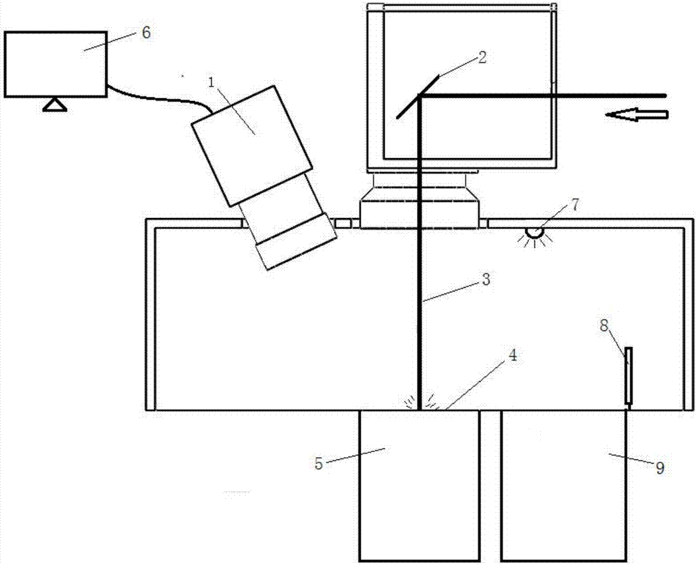
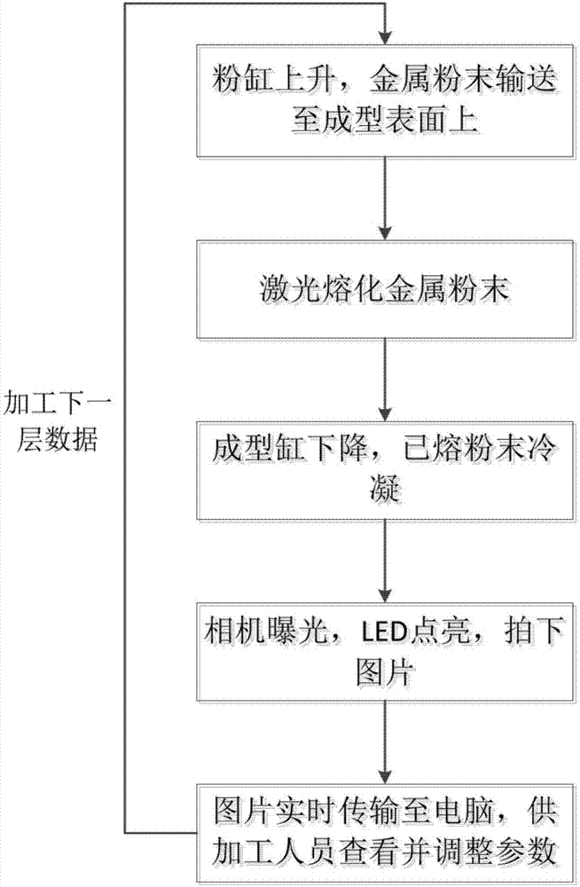
[0032] Such as figure 1 , figure 2 shown. The invention discloses a 3D printing process monitoring device based on camera real-time shooting, which includes a sealed molding room, a camera 1 is installed on the upper part of the sealed molding room, and the camera 1 monitors the shape of the 3D printing melting layer process through an opening in the upper part of the sealed molding room. A light source 7 is installed on the inner side of the top of the sealed molding chamber; the light source 7 is pulsed on when the camera 1 is exposed, and the light source 7 is turned off after the camera 1 is exposed, and the camera 1 transmits the layer shape data to the computer 6 in real time and store.

[0033] The pixel resolution of the camera is 1024×1024, 300 frames per second; the shortest exposure time of the overall shutter is 1us; the dynamic range is 120dB; the spectral range is 400-950nm, and the sampling resolution is 8 bits.

[0034] The light source 7 can be an LED ligh...


PUM


Abstract

The invention discloses a camera-based real-time shooting 3D printing process monitoring method and device. A camera is mounted on the upper portion of a sealing forming chamber and shoots the morphology in the molten layer 3D printing process. A light source is mounted on the inner side of the top of the sealing forming chamber. The light source is lightened in a pulse manner while exposure of the camera is achieved, the light source is extinguished after exposure of the camera is finished, and the morphology data of the layer are transmitted into a computer and stored in real time through the camera. By means of manual error analysis or intelligent error analysis, for defect parts existing in the printing process, the positions, time and reasons of defect generating can be accurately located, and effective bases are provided for optimizing and adjusting relevant parameters. The device is simple in structure and convenient to operate, integrity of data of each layer is guaranteed, process parameters are optimized, correction is achieved in time in the processing process, and part precision is greatly improved; or, after processing, by means of morphology analysis, problems existing in the processing process are found.

Description

technical field [0001] The invention relates to a laser selective melting process, in particular to a method and device for monitoring a 3D printing process based on real-time photography by a camera. Background technique [0002] Metal 3D printing technology has a lot of room for development in the manufacturing industry, but there are still many problems preventing its widespread use. In addition to the higher cost of metal 3D printers, there is a big problem with printing repeatability and quality control. At present, the research on the quality monitoring method of metal 3D printing at home and abroad is in the initial stage, and different types of equipment have different requirements on the molding conditions. For example, Arcam's EMB equipment requires strict monitoring of oxygen content and preheating temperature due to the strict requirements on the vacuum degree and temperature control in the molding chamber. In terms of SLM technology, some foreign teams monitor...

Claims


Application Information

Patent Timeline
Patent Type & Authority Applications(China)
IPC IPC(8): B22F3/105B33Y50/02B33Y30/00
CPCB33Y30/00B33Y50/02B22F10/00B22F12/42B22F12/90B22F10/28B22F10/366B22F10/80Y02P10/25
Inventor 王迪王艺锰杨永强林康杰
Owner SOUTH CHINA UNIV OF TECH
Learn More