A deep recovery device for boiler flue gas waste heat

A recovery device and boiler flue gas technology, which is applied in flue gas combustion, greenhouse gas reduction, climate sustainability, etc., can solve combustion instability and other problems, achieve the effects of reducing NOx generation, increasing dew point temperature, and normal flame

Active Publication Date: 2022-07-12
TSINGHUA UNIV
View PDF0 Cites 0 Cited by
  • Summary
  • Abstract
  • Description
  • Claims
  • Application Information

AI Technical Summary

Problems solved by technology

[0006] In view of the above problems, the purpose of the present invention is to provide a boiler flue gas waste heat that can not only increase the equivalent heat capacity of the air by humidifying the combustion air, recover more flue gas waste heat, but also solve the problem of unstable combustion caused by air droplets. Deep Recovery Unit

Method used


Image

  • A deep recovery device for boiler flue gas waste heat
  • A deep recovery device for boiler flue gas waste heat
  • A deep recovery device for boiler flue gas waste heat

Examples


Embodiment 1

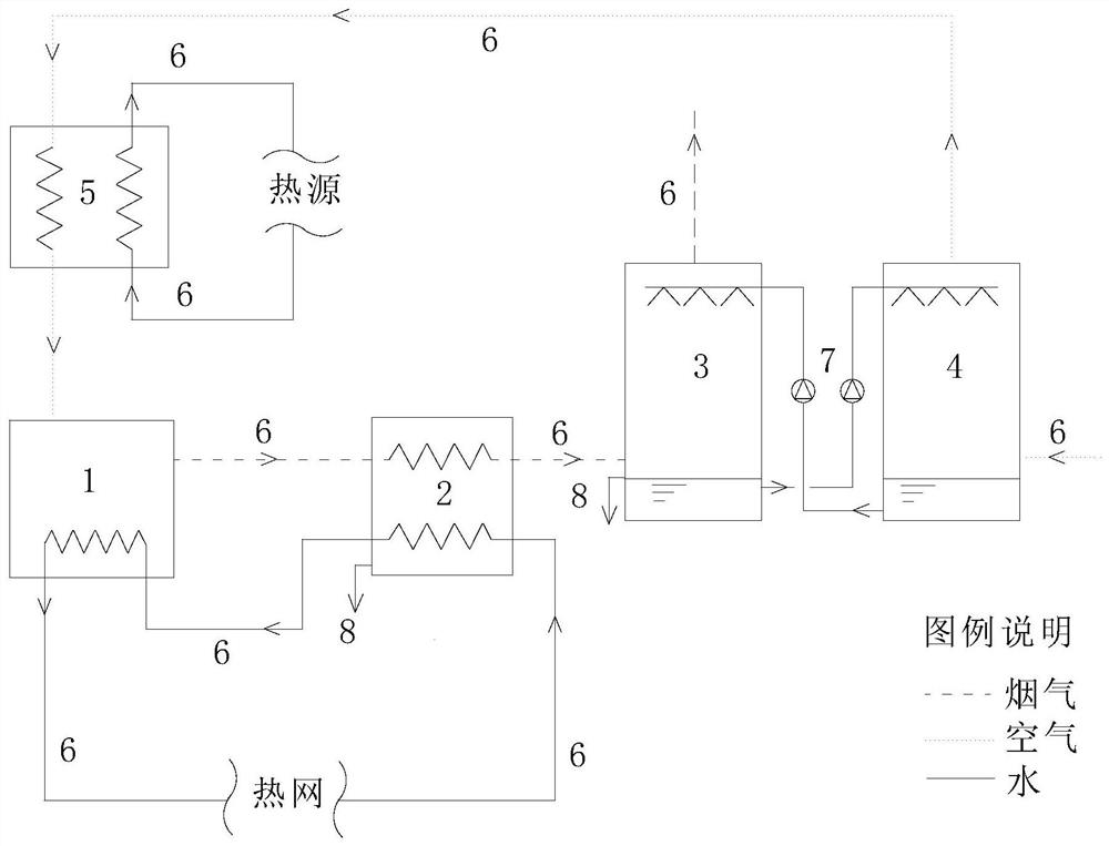
[0024] like figure 1 As shown, the boiler flue gas waste heat deep recovery device of the present invention comprises a boiler 1, a steam-water heat exchanger 2, a flue gas-water heat exchanger 3, an air-water heat exchanger 4, and an air reheater 5 , a number of pipes 6, a number of water pumps 7 and a number of overflow pipes 8.

[0025] figure 2 It is a schematic diagram of the overall structure of the boiler effluent as the heat source of the air reheater in Example 1 of the present invention. in:

[0026] The flue gas outlet of the boiler 1 is connected to the flue gas inlet of the steam-water heat exchanger 2 through the pipe 6a, and the flue gas outlet of the steam-water heat exchanger 2 is connected to the flue gas inlet of the flue gas-water heat exchanger 3 through the pipe 6b. The high-temperature flue gas in the boiler 1 passes through the steam-water heat exchanger 2 and the flue gas-water heat exchanger 3 for heat exchange in turn, and then is discharged into...

Embodiment 2

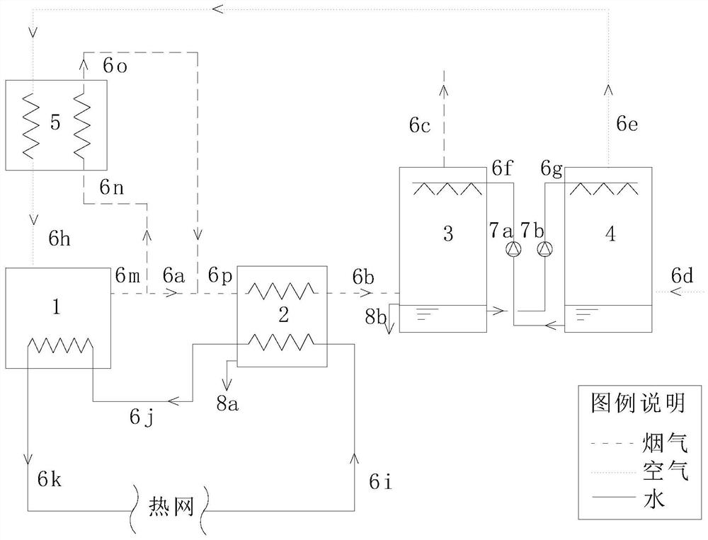
[0041] like Figure 5 As shown, the boiler flue gas waste heat deep recovery device of the present invention comprises a boiler 1, a steam-water heat exchanger 2, a flue gas-water heat exchanger 3, an air-water heat exchanger 4, and an air reheater 5 , a number of pipes 6, a number of water pumps 7 and a number of overflow pipes 8.

[0042] The flue gas outlet 6m of the boiler 1 is divided into two tributaries 6n and 6a, the tributary 6n is connected to the heat source inlet of the air reheater 5, and the flue gas is mixed with air in the air reheater 5, which is a gas mixing device , the air-flue gas mixture is connected to the air inlet of the boiler 1 through the pipeline 6h; the other branch 6a is connected to the flue gas inlet of the steam-water heat exchanger 2, and the flue gas outlet of the steam-water heat exchanger 2 is connected to the flue gas- The flue gas inlet of the water heat exchanger 3. The high-temperature flue gas in the boiler 1 passes through the stea...


PUM


Abstract

The invention relates to a deep recovery device for boiler flue gas waste heat, comprising a boiler, a steam-water heat exchanger, a flue gas-water heat exchanger, an air-water heat exchanger and an air reheater; the flue gas outlet of the boiler is connected to the steam-water heat exchange The flue gas inlet of the steam-water heat exchanger is connected to the flue gas inlet of the flue gas-water heat exchanger, and the air outlet of the air-water heat exchanger is connected to the air inlet of the air reheater. The air outlet is connected to the air inlet of the boiler; one water outlet of the steam-water heat exchanger is used for outward overflow, the other water outlet is connected to the water inlet of the boiler, and the water outlet of the boiler is connected to the return water inlet of the steam-water heat exchanger through the heat network; One water outlet of the air-water heat exchanger is used for outward overflow, the other water outlet is connected to the water inlet of the air-water heat exchanger, and the water outlet of the air-water heat exchanger is connected to the inlet of the flue gas-water heat exchanger. water outlet. The invention can increase the dew point temperature of the flue gas, recover more waste heat of the flue gas, lower the combustion temperature and reduce the NOx emission at the same time.

Description

technical field [0001] The invention relates to an energy recovery device, in particular to a deep recovery device for boiler flue gas waste heat recovery and reduction of nitrogen oxide emissions, belonging to the technical field of energy. Background technique [0002] Natural gas, oil, biomass and other fuels contain a large amount of hydrogen, and boiler combustion produces a large amount of water vapor, such as 1m 3 The combustion of natural gas will generate 1.55kg of water vapor, and the latent heat is about 3600kJ, accounting for 10% of the low-level calorific value of natural gas, but this part of the heat is often directly discharged into the atmosphere with the flue gas, causing waste of flue gas waste heat. Therefore, if the temperature of the flue gas can be lowered below the dew point and the part of the latent heat can be recovered, it will play an important role in saving fuel consumption. On the other hand, the flue gas generated by the boiler combustion con...

Claims


Application Information

Patent Timeline
Patent Type & Authority Patents(China)
IPC IPC(8): F23L15/00F23L7/00F23C9/00
CPCF23C9/00F23L7/00F23L15/00F23C2202/30Y02E20/34
Inventor 王静贻付林赵玺灵张世钢
Owner TSINGHUA UNIV
Why Eureka
Try Eureka