
Apparatus model for demonstrating building safety monitoring system

A technology for safety monitoring and monitoring modules, applied in the field of device models for demonstrating building safety monitoring systems, can solve problems such as loss of structural stability and bearing capacity, and inability to ensure residential and use safety, so as to reduce building safety accidents and promote large-scale applications. , The effect of improving the technical level of building safety monitoring

Pending Publication Date: 2017-06-27
BEIJING ZKTOP INFORMATION TECH CO LTD
View PDF0 Cites 1 Cited by
  • Summary
  • Abstract
  • Description
  • Claims
  • Application Information

AI Technical Summary

Problems solved by technology

[0003] Dangerous houses are dangerous houses. According to the "Urban Dangerous House Management Regulations", dangerous houses refer to houses whose structures have been seriously damaged or whose load-bearing components are already dangerous. They may lose structural stability and bearing capacity at any time, and cannot guarantee living and using safety.

Method used


Image

  • Apparatus model for demonstrating building safety monitoring system
  • Apparatus model for demonstrating building safety monitoring system
  • Apparatus model for demonstrating building safety monitoring system

Examples


Embodiment Construction

[0027] The present invention will be further described in conjunction with the accompanying drawings and specific embodiments.

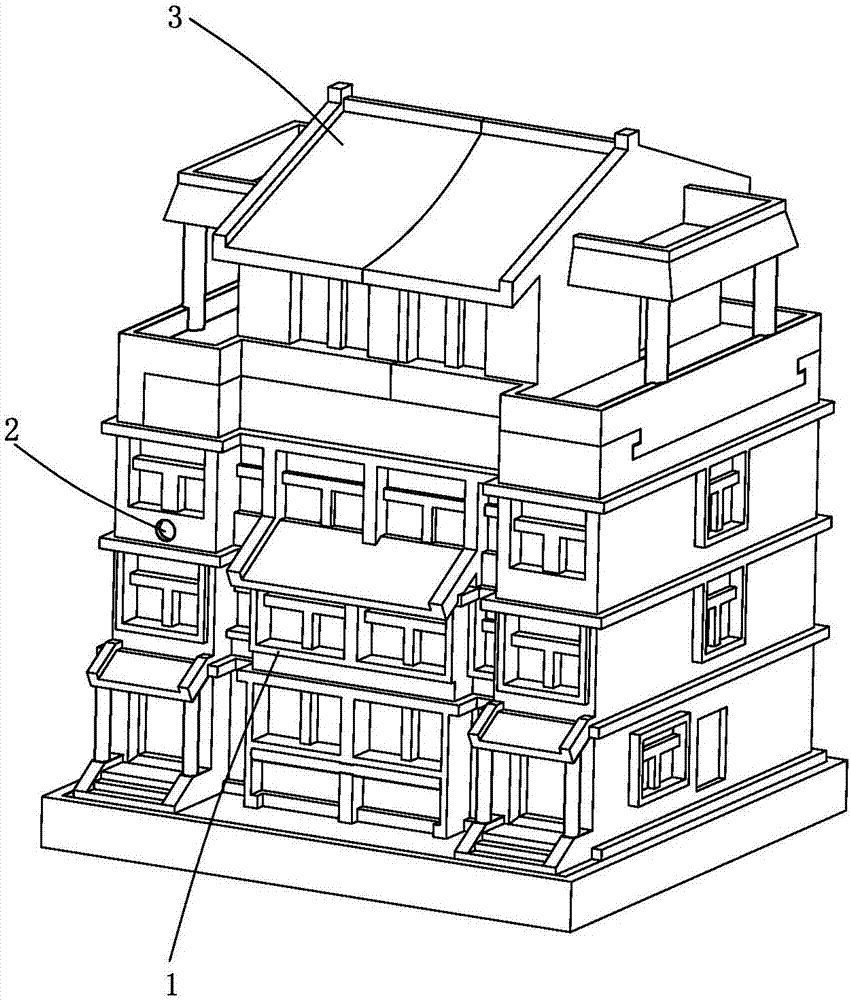
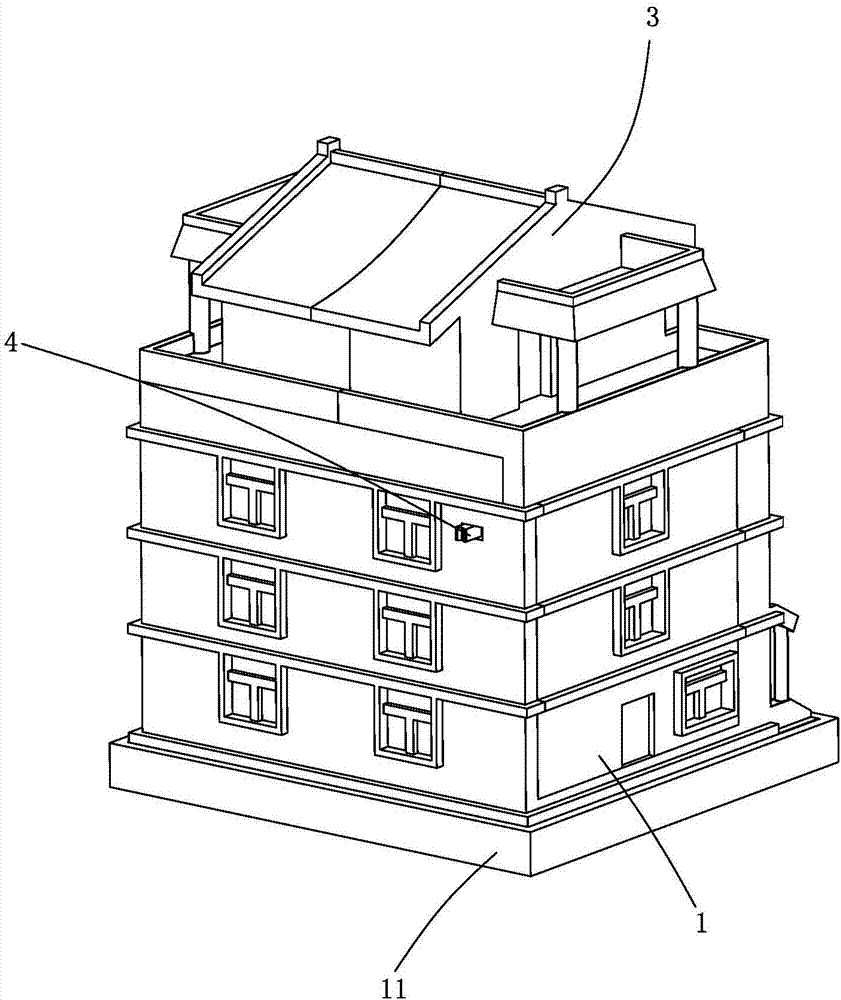
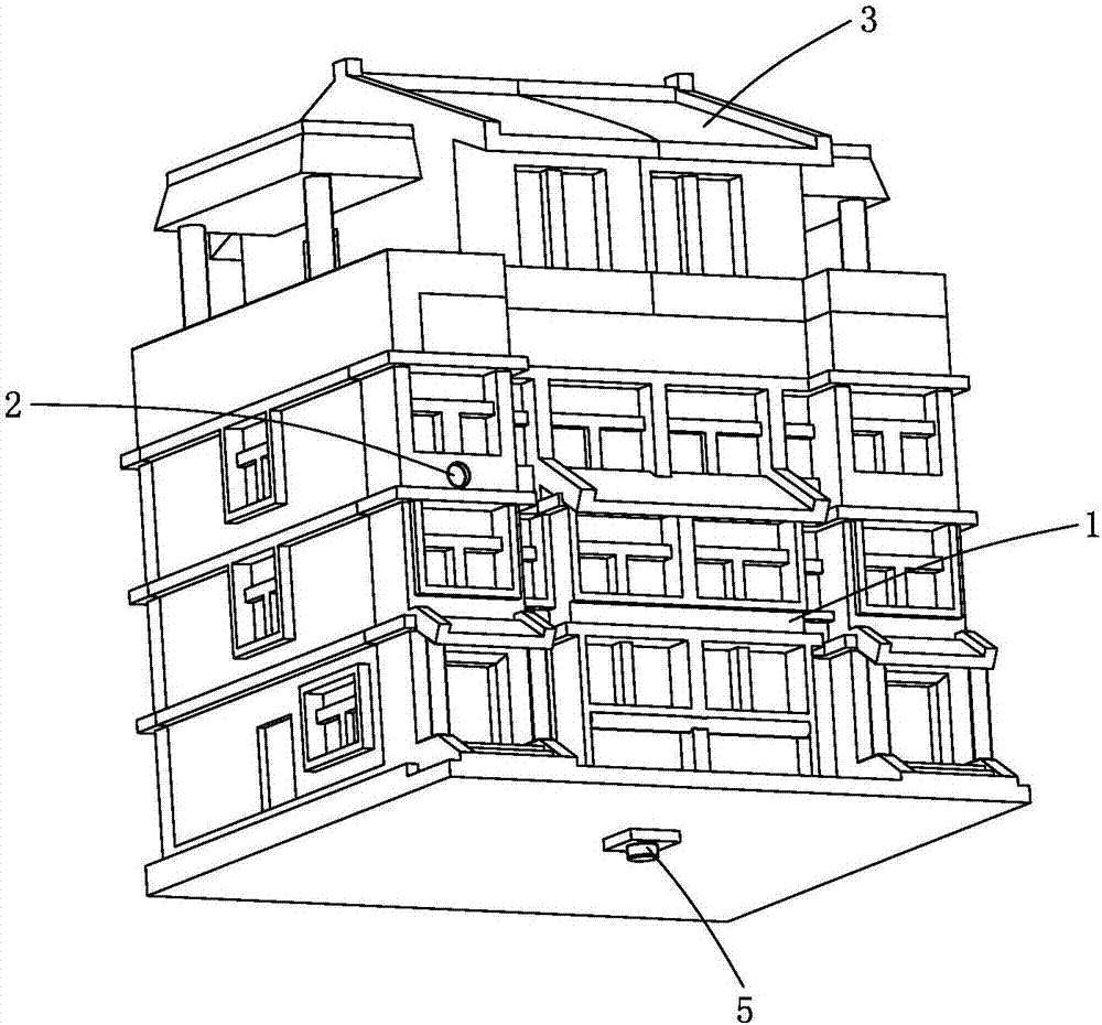
[0028] like Figure 1-7 As shown, a device model for demonstrating the building safety monitoring system includes a dangerous house model and a dangerous house state monitoring module, a power supply module 7, a communication module 14 and a main control circuit board 9 arranged on the dangerous house model, and the dangerous house state monitoring The output end of the module is connected to the input end of the main control circuit board 9, the output end of the power supply module 7 is connected to the power input end of the main control circuit board 9, and the communication module 14 is connected to the main control circuit board 9 for communication, and the main control circuit The board 9 communicates with the monitoring center 16 through the communication module 14 .

[0029] In this specific embodiment, the dilapidated house model is made b...


PUM


Abstract

The invention discloses an apparatus model for demonstrating a building safety monitoring system. The apparatus model for demonstrating a building safety monitoring system includes a dangerous building model, a dangerous building state monitoring module, a power supply module, a communication module and a main control circuit board, wherein the dangerous building state monitoring module, the power supply module, the communication module and the main control circuit board are arranged on the dangerous building model; an output end of the dangerous building state monitoring module is connected with an input end of the main control circuit board; an output end of the power supply module is connected with a power supply input end of the main control circuit board; the communication module is in communication connection with the main control circuit board; and the main control circuit board is in communication connection with a monitoring platform through the communication module. The apparatus model for demonstrating a building safety monitoring system can perform simulation continuous monitoring on the main indexes, such as inclination, non-uniform settlement and cracks of a building and timely capture the main characteristic information of change of properties of the building, and can send the monitoring data to a monitoring center in real time through a wireless mode, and then the monitoring center make a judgment and an early warning forecast for the integral stability of the building, and then the judgment and the early warning forecast are truly supplied to a user through a hand-held terminal (mobile phone) or a computer. Therefore, the apparatus model for demonstrating a building safety monitoring system has the advantages of being visual, being real-time, displaying dynamically, being small in volume, and being convenient to carry.

Description

technical field [0001] The invention belongs to the field of building safety monitoring, in particular to a device model for demonstrating a building safety monitoring system. Background technique [0002] In the 1980s and 1990s, both house design and construction were far behind the present. According to the regulations at that time, the load-bearing masonry structure at the bottom of the house did not have a moisture-proof layer. During the use, the brick foundation was soaked in rainwater for a long time, which made the wall wet, causing serious weathering of the load-bearing wall, and resulting in the collapse of the bottom wall due to insufficient strength. This is the conclusion drawn by experts based on the situation on the spot. [0003] Dangerous houses are dangerous houses. According to the "Urban Dangerous House Management Regulations", dangerous houses refer to houses whose structures have been severely damaged or whose load-bearing components are already danger...

Claims


Application Information

Patent Timeline
IPC IPC(8): G01D21/02
CPCG01D21/02
Inventor 洪毅刘浩王鑫堂王福锦马启鹏
Owner BEIJING ZKTOP INFORMATION TECH CO LTD
Learn More