Press fit device for LED lamp bracket glue dispensing
A technology of an LED lamp holder and a pressing device, which is applied in the field of pressing devices, can solve the problems of low work efficiency, affecting the use of the LED lamp holder, and poor pressing effect, and achieves the effect of improving the pressing effect.
- Summary
- Abstract
- Description
- Claims
- Application Information
AI Technical Summary
Problems solved by technology
Method used
Image
Examples
Embodiment 1
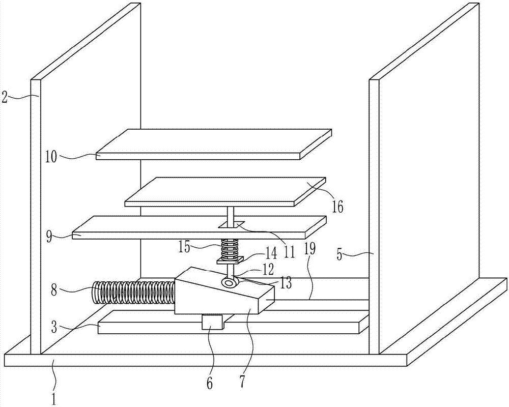
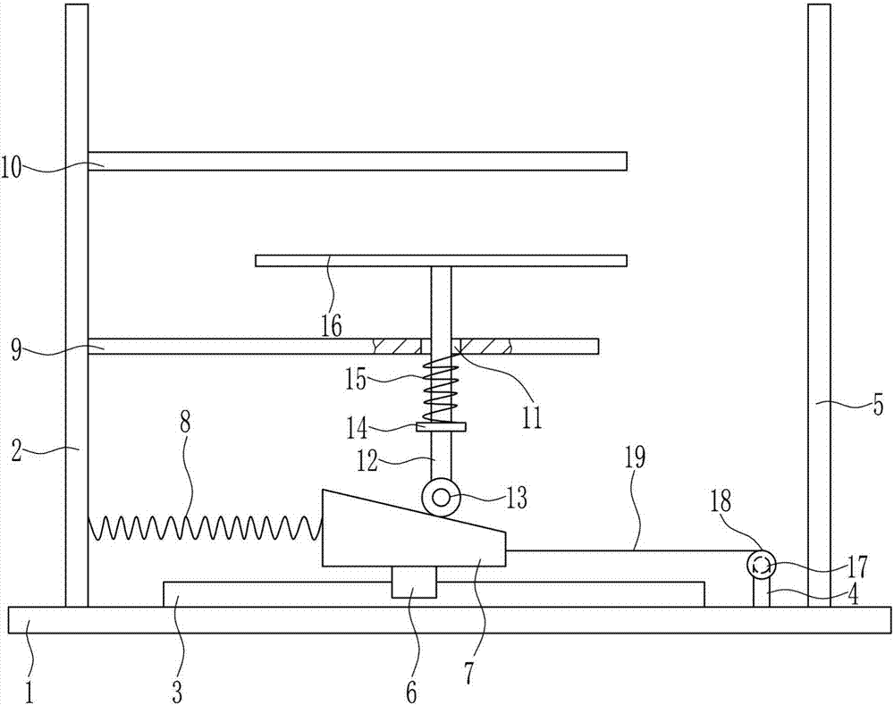
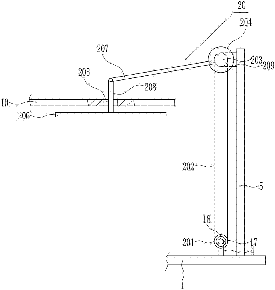
[0033] A pressing device for LED light frame dispensing, such as Figure 1-6 As shown, it includes a bottom plate 1, a left side plate 2, a slide rail 3, a pole 4, a right side plate 5, a first slider 6, a wedge block 7, a first spring 8, a guide plate 9, a connecting plate 10, a guide plate Rod 12, contact roller 13, fixed baffle 14, second spring 15, first pressure plate 16, first motor 17, winding wheel 18 and first pull wire 19, the top of bottom plate 1 is connected by bolts in sequence from left to right The left side plate 2, the slide rail 3, the strut 4 and the right side plate 5 are installed, the slide rail 3 is provided with the first slide block 6 matched with it, and the top of the first slide block 6 is connected with a wedge-shaped block by means of bolts 7. A first spring 8 is connected between the wedge-shaped block 7 and the left side plate 2, and a first motor 17 is installed on the top of the strut 4 through bolt connection, and the output shaft of the fir...
Embodiment 2
[0035] A pressing device for LED light frame dispensing, such as Figure 1-6 As shown, it includes a bottom plate 1, a left side plate 2, a slide rail 3, a pole 4, a right side plate 5, a first slider 6, a wedge block 7, a first spring 8, a guide plate 9, a connecting plate 10, a guide plate Rod 12, contact roller 13, fixed baffle 14, second spring 15, first pressure plate 16, first motor 17, winding wheel 18 and first pull wire 19, the top of bottom plate 1 is connected by bolts in sequence from left to right The left side plate 2, the slide rail 3, the strut 4 and the right side plate 5 are installed, the slide rail 3 is provided with the first slide block 6 matched with it, and the top of the first slide block 6 is connected with a wedge-shaped block by means of bolts 7. A first spring 8 is connected between the wedge-shaped block 7 and the left side plate 2, and a first motor 17 is installed on the top of the strut 4 through bolt connection, and the output shaft of the fir...
Embodiment 3
[0038] A pressing device for LED light frame dispensing, such as Figure 1-6 As shown, it includes a bottom plate 1, a left side plate 2, a slide rail 3, a pole 4, a right side plate 5, a first slider 6, a wedge block 7, a first spring 8, a guide plate 9, a connecting plate 10, a guide plate Rod 12, contact roller 13, fixed baffle 14, second spring 15, first pressure plate 16, first motor 17, winding wheel 18 and first pull wire 19, the top of bottom plate 1 is connected by bolts in sequence from left to right The left side plate 2, the slide rail 3, the strut 4 and the right side plate 5 are installed, the slide rail 3 is provided with the first slide block 6 matched with it, and the top of the first slide block 6 is connected with a wedge-shaped block by means of bolts 7. A first spring 8 is connected between the wedge-shaped block 7 and the left side plate 2, and a first motor 17 is installed on the top of the strut 4 through bolt connection, and the output shaft of the fir...
PUM
 Abstract
Description
Claims
Application Information
 - R&D Engineer
- R&D Manager
- IP Professional
- Industry Leading Data Capabilities
- Powerful AI technology
- Patent DNA Extraction
Browse by: Latest US Patents, China's latest patents, Technical Efficacy Thesaurus, Application Domain, Technology Topic, Popular Technical Reports.
© 2024 PatSnap. All rights reserved.Legal|Privacy policy|Modern Slavery Act Transparency Statement|Sitemap|About US| Contact US: help@patsnap.com


