
Novel FRP profile chamfering block and application thereof

A profile and chamfering technology, applied in building maintenance, construction, building construction, etc., can solve problems such as difficulties, small strain values, and concentration, so as to improve bearing capacity and deformation capacity, increase cross-sectional contact area, and avoid local damage Effect

Inactive Publication Date: 2017-06-27
BEIJING UNIVERSITY OF CIVIL ENGINEERING AND ARCHITECTURE
View PDF5 Cites 2 Cited by
  • Summary
  • Abstract
  • Description
  • Claims
  • Application Information

AI Technical Summary

Problems solved by technology

[0003] For reinforced concrete square columns wrapped by traditional methods, the full tensile capacity of FRP cloth is not effectively reflected in the restrained column. The main reasons are as follows: (1) FRP cloth itself will produce curvature when FRP cloth wraps the member; (2) for As far as the FRP fabric is stretched directly, the constrained FRP fabric is not in a pure tension state; (3) The cracked concrete under the FRP package produces uneven deformation and local stress concentration, which is caused by local defects during the wet laying process; (4) The minimum strain value measured in the overlapping area leads to uneven strain distribution around it
[0004] Rectangular cross-section columns generally need to grind the four right angles of the column into rounded corners before wrapping FRP cloth, which can greatly reduce the stress concentration at the corners and improve the restraint effect, but there are still the following disadvantages: (1) causing additional costs (2 ) The construction is relatively difficult (3) It cannot be applied to the reinforcement of existing reinforced concrete members

Method used


Image

  • Novel FRP profile chamfering block and application thereof
  • Novel FRP profile chamfering block and application thereof
  • Novel FRP profile chamfering block and application thereof

Examples


Embodiment Construction

[0025] Embodiments of the present invention will be further described in detail below in conjunction with the accompanying drawings and examples. The following examples are used to illustrate the present invention, but should not be used to limit the scope of the present invention.

[0026] In the description of the present invention, unless otherwise stated, the meaning of "multilayer" is two or more; the terms "upper", "lower", "left", "right", "inner", "outer" The orientation or positional relationship indicated by etc. is based on the orientation or positional relationship shown in the drawings, and is only for the convenience of describing the present invention and simplifying the description, rather than indicating or implying that the referred device or element must have a specific orientation, use a specific Azimuth configuration and operation, therefore, should not be construed as limiting the invention.

[0027] Such as figure 1 , 2 As shown, this embodiment provi...


PUM

PropertyMeasurementUnit
Heightaaaaaaaaaa

Abstract

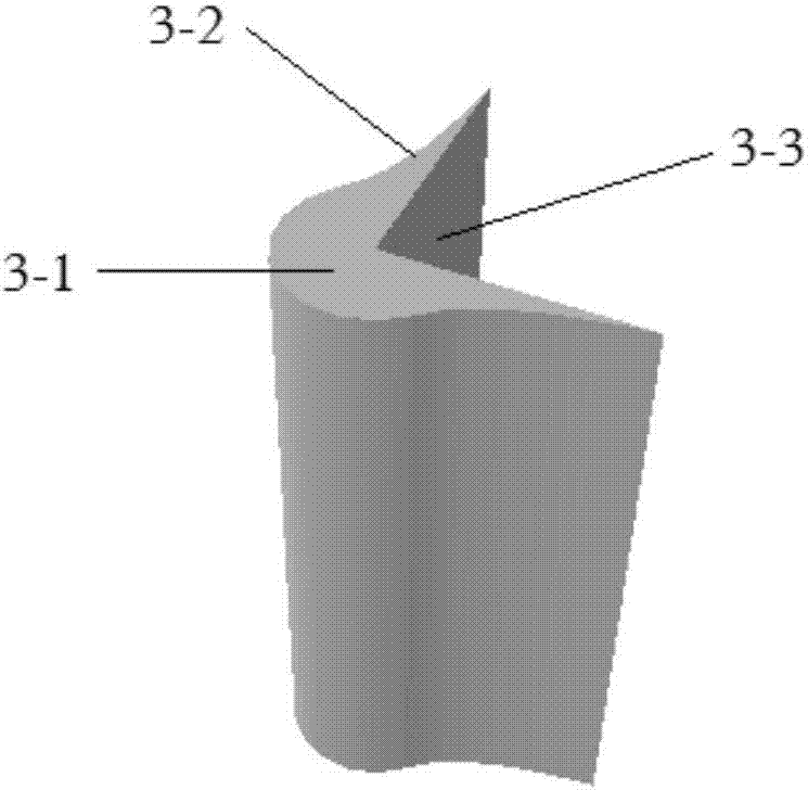
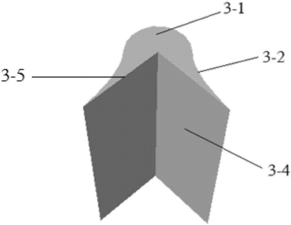
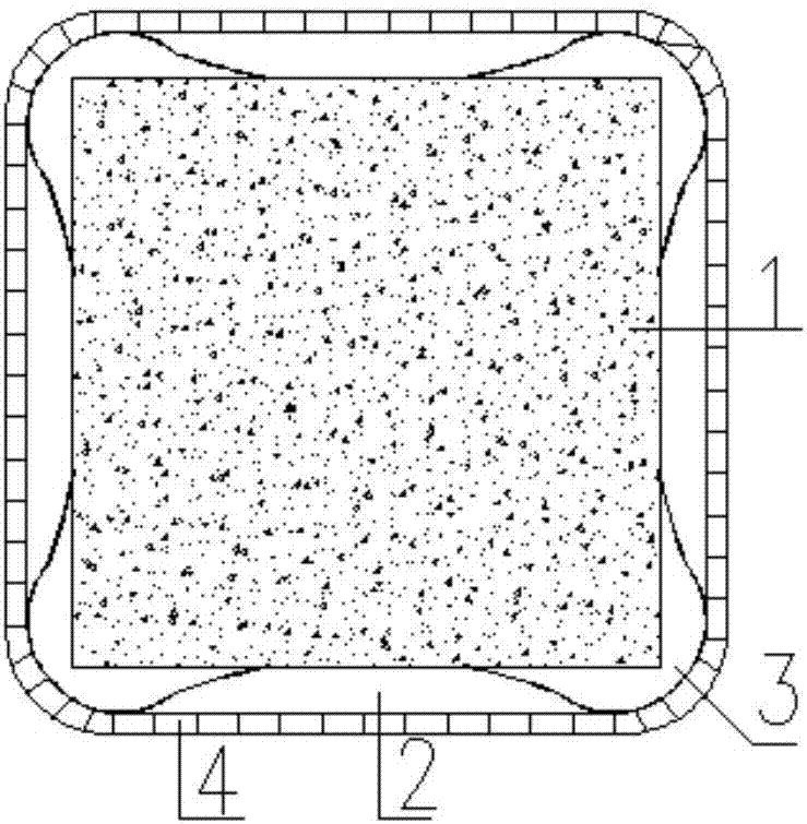
The invention relates to the field of civil engineering, in particular to a novel FRP profile chamfering block and its application. The chamfering block includes a cylindrical body, the body is axially provided with a right-angle groove through the body, the two right-angle faces of the right-angle groove extend outside the body, and transition sections are filled between the body and the two right-angle surfaces of the right-angle groove, , right-angle groove and transition section are integrally formed, and the material is FRP. The present invention also provides a reinforcement method for reinforced concrete rectangular columns, namely: paste the right-angled grooves of the FRP profile chamfering blocks on the corners of the rectangular columns from top to bottom along the height of the column, and between adjacent chamfering blocks in the horizontal direction The gap between them is filled with epoxy resin, and then the chamfering block is wrapped with FRP cloth. With this chamfering block, the rectangular column no longer needs to be chamfered during reinforcement, which fundamentally solves the difficulty of chamfering the rectangular column, greatly reducing the extra cost of reinforcement; and solves the FRP caused by the stress concentration of the chamfering Problem with cloth being pulled off prematurely.

Description

technical field [0001] The invention relates to the field of civil engineering, in particular to a novel FRP profile chamfering block and its application. Background technique [0002] Fiber Reinforced Plastics (FRP) is a new type of material formed by mixing fiber materials and matrix materials (resin) in a certain proportion. It has many excellent properties such as light weight, high strength, corrosion resistance, and fatigue resistance. It is widely used in civil engineering, not only for the reinforcement of existing structures, but also for new structures. The basic principle of FRP reinforcement technology is: when the reinforced concrete rectangular column is subjected to axial load, it will expand laterally, and the FRP fabric will generate tensile stress, which provides lateral constraints on the core concrete, making the concrete in a stress state of three-dimensional compression, thereby increasing the core strength. The compressive strength and deformation cap...

Claims


Application Information

Patent Timeline
IPC IPC(8): E04G23/02
CPCE04G23/0218E04G2023/0251
Inventor 王作虎刘杜崔宇强杨文雄
Owner BEIJING UNIVERSITY OF CIVIL ENGINEERING AND ARCHITECTURE
Learn More