
Tile-shaped magnet forming die, magnet forming method and motor magnet

A molding die and molding method technology are applied in the fields of tile-shaped magnet molding die and motor magnet, and can solve the problems of low production efficiency of direct pressing and molding of magnetic products, etc.

Active Publication Date: 2017-06-27
BEIJING ZHONG KE SAN HUAN HI TECH
View PDF5 Cites 0 Cited by
  • Summary
  • Abstract
  • Description
  • Claims
  • Application Information

AI Technical Summary

Problems solved by technology

[0006] The first object of the present invention is to provide a tile-shaped magnet molding die to solve the technical problem of low production efficiency of direct compression molding magnetic products

Method used


Image

  • Tile-shaped magnet forming die, magnet forming method and motor magnet
  • Tile-shaped magnet forming die, magnet forming method and motor magnet
  • Tile-shaped magnet forming die, magnet forming method and motor magnet

Examples


Embodiment Construction

[0046] Hereinafter, embodiments of a shoe-shaped magnet forming die and a magnet forming method of the present invention will be described with reference to the accompanying drawings.

[0047] The examples described here are specific specific implementations of the present invention, and are used to illustrate the concept of the present invention. They are all explanatory and exemplary, and should not be construed as limiting the implementation of the present invention and the scope of the present invention. In addition to the embodiments described here, those skilled in the art can also adopt other obvious technical solutions based on the claims of the application and the contents disclosed in the description, and these technical solutions include adopting any obvious changes made to the embodiments described here. Replacement and modified technical solutions.

[0048] The accompanying drawings in this specification are schematic diagrams, which assist in explaining the conce...


PUM


Abstract

The invention discloses a tile-shaped magnet forming die and a magnet forming method. The die comprises a first side plate, a second side plate, a bottom press head, a top press head and a stop block, wherein a first side plate bulge part is arranged on the first side plate; the structure of the second side plate and the structure of the first side plate are mirror images; a bottom press head bulge part is arranged at one end of the bottom press head, and the structure of the bottom press head bulge part is the same as the structure of a cavity encircled by one half divided by a central line, of a second magnet pair, and the second magnet pair; a top press head bulge part is arranged at one end of the top press head, and the structure of the top press head bulge part is the same as the structure of a cavity included by the second curved surfaces of two tile-shaped magnets of the second magnet pair; and the shape of the stop block is the same as the structure of a cavity encircled by the first curved surfaces of the two tile-shaped magnets of a first magnet pair. According to the tile-shaped magnet forming die and the magnet forming method, the problem of low production efficiency of direct pressing forming for a magnetic product and the problem that a tile space is not easily fully filled with a magnetic powder due to a small size are solved; and meanwhile, the sintered magnets have a low working allowance, and a high material yield is achieved.

Description

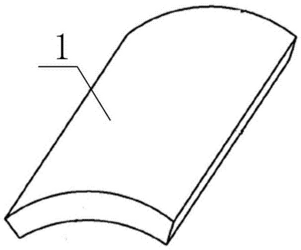
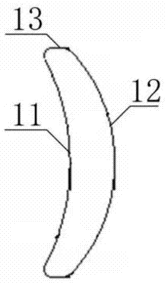
technical field [0001] The invention belongs to the technical field of magnet forming, and in particular relates to a tile-shaped magnet forming mold, a magnet forming method realized by the mold, and a motor magnet. Background technique [0002] Permanent magnet motors have been widely used in recent years due to their small size, light weight and strong magnetic properties. Then, as an important part of it, tile-shaped rare earth permanent magnets, especially NdFeB magnets, are as attached figure 1 As shown, it is not easy to process and shape due to the existence of the arc surface. [0003] For tile-shaped magnets, block magnets are usually used in the industry to cut and shape them with ring cutters or wire saws. These two methods have two shortcomings. On the one hand, due to the poor fluidity of the magnetic powder, the density of the magnetic powder is uneven when forming a large magnet, and the consistency of the processed magnet is poor; on the other hand, the ut...

Claims


Application Information

Patent Timeline
IPC IPC(8): B22F3/03B22F3/16
CPCB22F3/03B22F3/16
Inventor 侯德柱吴晓平王东明王进东史学伟
Owner BEIJING ZHONG KE SAN HUAN HI TECH
Learn More