
Heat pipe radiator with variable-section hot end and multiple pulsation cold ends

A heat pipe radiator and variable cross-section technology, applied in the field of strengthening heat transfer, can solve problems such as affecting the heat dissipation effect, adding multiple solder joints, and lack of organic combination, so as to improve the heat and mass transfer performance, expand the cooling area of ​​the cold end, The effect of increasing the pressure bearing capacity

Active Publication Date: 2017-06-23
CHANGSHA UNIVERSITY OF SCIENCE AND TECHNOLOGY
View PDF15 Cites 7 Cited by
  • Summary
  • Abstract
  • Description
  • Claims
  • Application Information

AI Technical Summary

Problems solved by technology

First, because the cold and hot ends of the heat pipe are taken from the upper and lower end surfaces of the heat pipe, not the large-scale direction of the internal space, the overall flow of the working fluid is in the up-down direction, and the up-down distance is very short, which means that the convection effect that is beneficial to heat transfer is basically It does not exist, which affects the heat transfer effect of the working fluid side, thus weakening the overall heat transfer capacity of the heat pipe
The second is that as a simple flat heat pipe, it is impossible to arrange a larger heat dissipation area in a limited area, so that the heat dissipation area is not enough
The third is that the flat heat pipe does not use pulsating heat transfer with stronger heat transfer capacity, it is not a pulsating heat pipe, and the evaporation end can only be installed horizontally
However, it has the following disadvantages during its use: First, there is no reinforced structure inside the plate in the evaporating section, which is easy to bulge and deform after being pressed, thus affecting the contact with the heating element; When increasing the condensing section, that is, increasing the number of heat dissipation areas, the upper and lower planes must be enlarged at the same time, causing the area of ​​the lower plane (that is, the contact surface) to be much larger than the area of ​​the cooled body, which violates the requirement of a small area occupied by the plane heating body cooling device; the third is the inside of the heat pipe There is no pulsation channel, and the pulsation heat transfer with stronger heat transfer capacity cannot be applied. Fourth, the heat pipe is actually a horizontal flat heat pipe, which is not suitable for the heat dissipation of the vertical plane heating element.
The analysis found that the patent has the following deficiencies: First, the flat box in the evaporating section adopts additional support to improve the pressure resistance, which cannot guarantee the effect as a thin-walled box, and will increase multiple solder joints, which is not conducive to processing and forming a vacuum; 3. The second and third points corresponding to ZL200820224845.9 are the same; 4. The direction of the fins of the flat tubes in the condensation section is perpendicular to the axis of the flat tubes. The fins can only be welded and cannot be integrally stretched with the flat tubes. Processing is very complex
[0013] The analysis found that the use process would have the following shortcomings: First, the flat box in the evaporation section adopts the patented support to improve the pressure resistance and prevent deformation, the effect cannot be guaranteed, and it will increase multiple solder joints, which is not conducive to the formation of a vacuum; 3. The second and third points corresponding to ZL200820224845.9 are the same; 4. The cross-section of the flow channel in the condensation section is rectangular, and the condensate will flow down vertically along the large side wall under the action of gravity, and then concentrate from the lower part of the condensation end Flowing into the lower part of the evaporation end, this concentrated backflow will lead to a lack of working fluid in the upper part of the evaporation part and an increase in temperature, which will also make the temperature of the upper part of the cooled electronic device higher and uneven, which will endanger the safety of the electronic device; The axial direction of the flat tube is vertical, the fins cannot be integrally stretched and formed with the flat tube, and the processing is very complicated
[0014] It can be seen from the above public information that the heat pipe involved has defects in structure or heat transfer principle, resulting in poor heat dissipation effect, and cannot well meet the heat dissipation requirements of the high heat flux planar heating element. The common defects are: 1 , It cannot or cannot be used for the heat dissipation of vertical chips, and it cannot be used both horizontally and vertically; 2. There is no difference in the cross-sectional area of ​​​​the hot end, and the relationship between reducing the heat-absorbing contact area and expanding the heat-dissipating area cannot be coordinated; 3. The two thermal processes of evaporation and condensation The same heat transfer mechanism is used, and the processes of different mechanisms are not organically combined, which affects the heat dissipation effect; 4. The heat pipe pressure problem is not solved ideally, which affects the heat dissipation effect and the product quality of the radiator; 5. There are no problems with uniform backflow and temperature uniformity Reasonable handling

Method used


Image

  • Heat pipe radiator with variable-section hot end and multiple pulsation cold ends
  • Heat pipe radiator with variable-section hot end and multiple pulsation cold ends
  • Heat pipe radiator with variable-section hot end and multiple pulsation cold ends

Examples


Embodiment 1

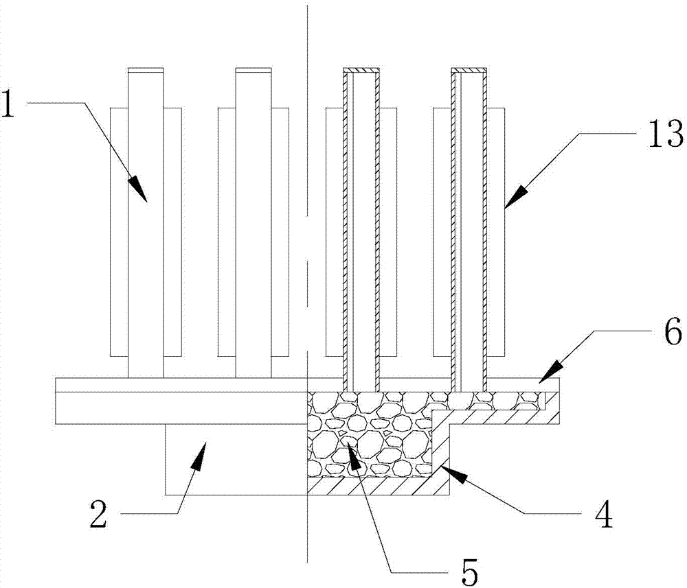
[0051] See attached figure 1 , 2 , 3, 4, 5, 6, a hot-end variable cross-section multi-pulsation cold-end heat pipe radiator, the hot-end variable cross-section multi-pulsation cold-end heat pipe radiator includes a pulsating cold end 1 and a hot end 2, in the The pulsating cold end 1 is provided with a plurality of heat dissipation plates with pulsating passages 3; the hot end is a hollow cavity 4, which is filled with working fluid and capillary liquid-absorbing core 5; the hot end is hollow The upper cover plate 6 of the cavity 4 is provided with a plurality of cold end interfaces 7, and each cold end interface 7 is equipped with a pulsating cold end 1, so that the pulsating channel 3 of the pulsating cold end 1 and the hollow cavity of the hot end 2 body 4 connected;

[0052] The area of ​​the upper cover plate 6 of the hot-end hollow cavity 4 is 2.5 times the area of ​​the lower cover plate 8, and two right-angle pressure-bearing hoops with large compressive capacity are...

Embodiment 2

[0065] See attached Figure 7 , 8 , a hot-end variable cross-section multi-pulsation cold-end heat pipe radiator, the hot-end variable-section multi-pulsation cold-end heat pipe radiator includes a pulsating cold end 1 and a hot end 2, and multiple pulsating cold ends 1 are provided The heat dissipation plate body of the pulsating channel 3; the hot end is a hollow cavity 4, which is filled with working fluid and capillary liquid-absorbing core 5; on the upper cover plate 6 of the hollow cavity 4 of the hot end A plurality of cold end interfaces 7 are provided, and each cold end interface 7 is equipped with a pulsating cold end 1, so that the pulsating channel 3 of the pulsating cold end 1 communicates with the hollow cavity 4 of the hot end 2;

[0066] The area of ​​the upper cover plate 6 of the hot-end hollow cavity 4 is 2.0 times the area of ​​the lower cover plate 8, and two right-angle pressure-bearing hoops with large compressive capacity are added by adopting the step...

Embodiment 3

[0079] See attached Figure 9 , 10 , 11. A hot-end variable cross-section multi-pulsation cold-end heat pipe radiator, the hot-end variable-section multi-pulse cold-end heat pipe radiator includes a pulsating cold end 1 and a hot end 2, and the pulsating cold end 1 is provided with The heat dissipation plate body of a plurality of pulsating channels 3; the hot end is a hollow cavity 4, which is filled with working fluid and capillary liquid-absorbing core 5; the upper cover plate of the hollow cavity 4 at the hot end 6 is provided with a plurality of cold end interfaces 7, and each cold end interface 7 is equipped with a pulsating cold end 1, so that the pulsating channel 3 of the pulsating cold end 1 communicates with the hollow cavity 4 of the hot end 2;

[0080] The area of ​​the upper cover plate 6 of the hot-end hollow cavity 4 is 3.5 times the area of ​​the lower cover plate 8, and two right-angle pressure-bearing sides with large compressive capacity are added by adopt...


PUM

PropertyMeasurementUnit
Equivalent diameteraaaaaaaaaa

Abstract

The invention provides a heat pipe radiator with a variable-section hot end and multiple pulsation cold ends. The heat pipe radiator with the variable-section hot end and the multiple pulsation cold ends comprises the pulsation cold ends and the hot end. The heat pipe radiator with the variable-section hot end and the multiple pulsation cold ends is characterized in that each pulsation cold end is a heat dissipating plate internally provided with multiple pulsation channels, the hot end is a hollow cavity, the cavity is filled with a working medium and a capillary liquid absorbing core, an upper cover plate of the hot end hollow cavity is provided with multiple cold end connectors, each cold end connector is provided with one pulsation cold end, and the pulsation channels of the pulsation cold ends communicate with the hollow cavity of the hot end. The heat pipe radiator with the variable-section hot end and the multiple pulsation cold ends is simple in structure, easy to manufacture and capable of being transversely and vertically used, the variable-section structure is adopted, so that the pressure bearing capacity of heat pipes can be improved, especially the heat dissipating area of the cold ends is increased, the two thermal processes of evaporation and condensation adopt a pulsation heat transferring mode and a porous medium heat transferring mode correspondingly, the heat transferring performance and the medium transferring performance are effectively improved, backflow is uniform, the temperature uniformity is good, and the heat pipe radiator with the variable-section hot end and the multiple pulsation cold ends is suitable for industrial manufacturing.

Description

technical field [0001] The invention discloses a hot-end variable-section multi-pulse cold-end heat pipe radiator, which belongs to the technical field of heat transfer enhancement. [0002] technical background [0003] Driven by the objective trend of technological development, some crucial microelectronic and optoelectronic components, such as large-scale integrated circuit chips in the IC field, TR components of active phased array radar in the military field, LED chips in the lighting field, and laser field The pumping source and gain medium of the high-power solid-state laser, the concentrating photovoltaic cell in the photovoltaic field, etc., have been developing rapidly towards the path of high speed, integration and miniaturization. At the same time, an unavoidable problem appeared immediately, that is, the heating problem during operation, which caused the components to run unstable or even burn out. Therefore, from the perspective of heat transfer, such devices ca...

Claims


Application Information

Patent Timeline
IPC IPC(8): F28D15/04
CPCF28D15/04
Inventor 夏侯国伟
Owner CHANGSHA UNIVERSITY OF SCIENCE AND TECHNOLOGY
Learn More