
Transformer winding bobbin

A technology for winding bobbins and transformers, applied in the direction of transformer/inductor coil/winding/connection, transformer/inductor components, electrical components, etc. and other problems, to achieve the effect of improving the way of winding, improving the efficiency of assembly and processing, and improving the processing efficiency.

Inactive Publication Date: 2017-06-20
ZHUHAI LIMING YUNLU NEW ENERGY TECH
View PDF8 Cites 0 Cited by
  • Summary
  • Abstract
  • Description
  • Claims
  • Application Information

AI Technical Summary

Problems solved by technology

Originally, the tail wires of transformer shielding windings were usually cut and buried in the copper wire package in order to fix them conveniently. Operators were required to insert the tail wires. However, this method of embedding wires cannot be automated, and the operation is inconvenient and takes a lot of man-hours, which greatly affects The processing efficiency is improved, and when the tail wire is not handled well, the tail wire discharges in the copper wire bag, which is very easy to cause the short circuit of the copper wire bag and cause serious use consequences.

Method used


Image

  • Transformer winding bobbin
  • Transformer winding bobbin

Examples


Embodiment Construction

[0018] The idea, specific structure and technical effects of the present invention will be clearly and completely described below in conjunction with the embodiments and accompanying drawings, so as to fully understand the purpose, features and effects of the present invention. Apparently, the described embodiments are only some of the embodiments of the present invention, rather than all of them. Based on the embodiments of the present invention, other embodiments obtained by those skilled in the art without creative efforts belong to The protection scope of the present invention.

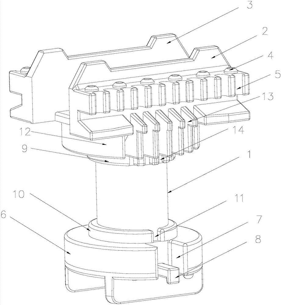
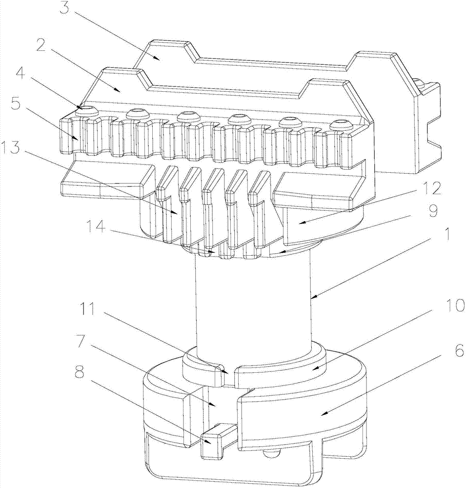
[0019] refer to figure 1 and figure 2 , a transformer winding bobbin, including a primary end 2, a secondary end 3 and a winding shaft 1, the winding shaft 1 is a hollow cylinder, and the hollow structure reduces the weight of the winding shaft 1. The primary end 2 and the secondary end 3 are respectively fixed on the two sides facing each other at the upper end of the winding shaft 1, and seve...


PUM


Abstract

The invention discloses a transformer winding bobbin. The transformer winding bobbin comprises a primary end, a secondary end and a winding shaft, wherein the primary end and the secondary end are fixed on two opposite sides of the upper end of the winding shaft respectively; a plurality of PIN seats are fixed to each of the primary end and the secondary end; a plurality of first lead wire grooves are formed in the outer surface of each of the primary end and the secondary end; a lower baffle is arranged at the lower end of the winding shaft; a tail wire lead-down groove is formed in the lower baffle; a hook block is arranged in the tail wire lead-down groove; a tail wire of a wire group is pulled out of the tail wire lead-down groove formed in the lower baffle; and the tail wire is wound around the hook block to be fixed, so that the tail wire does not need to be buried in a copper coil, a short circuit is difficultly caused, the safety performance of the wire group is improved, a winding mode is improved, automated winding can be realized, and the assembling processing efficiency is improved.

Description

technical field [0001] The invention relates to the field of electrical equipment, in particular to a low-power high-frequency transformer, in particular to a transformer winding skeleton. Background technique [0002] The high-frequency transformer is the most important part of the switching power supply. The transformer skeleton is the main structural part of the electronic transformer. Its main function is to provide winding space for the shielding winding in the transformer, and the insulation performance of the transformer shielding winding is to affect the transformer. important factor in job performance. Originally, the tail wires of transformer shielding windings were usually cut and buried in the copper wire package in order to fix them conveniently. Operators were required to insert the tail wires. However, this method of embedding wires cannot be automated, and the operation is inconvenient and takes a lot of man-hours, which greatly affects The processing effici...

Claims


Application Information

Patent Timeline
Patent Type & Authority Applications(China)
IPC IPC(8): H01F27/30H01F27/29
CPCH01F27/306H01F27/29
Inventor 叶贵辉陈晋海黄巧丽
Owner ZHUHAI LIMING YUNLU NEW ENERGY TECH
Learn More