


Quick Research
Generate reliable direction feasibility study reports for your R&D in just a few steps.

Technical Q&A
Discover and master advanced knowledge NOW. Basics, ideas, possibilities, all at once.

Find Solutions
As an expert in R&D theories, this can generate solutions to your technical problems instantly.

Evaluate Feasibility
Analyze your overall solution with one click, know your potential R&D risks in advance.

Monitor Landscape
Get weekly tech updates, stay abreast of the latest tech innovations and key insights.
A lens fixing structure
A technology for fixing structures and lenses, applied in instruments, installations, optics, etc., to solve the problems of insensitive adjustment, incompatibility, and inability to achieve
- Summary
- Abstract
- Description
- Claims
- Application Information
AI Technical Summary
Problems solved by technology
Method used
Image

Examples
Embodiment 1
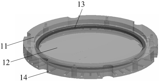
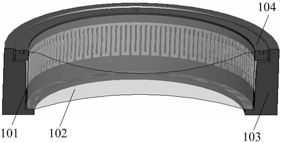
[0029] like image 3 and 4 As shown, the lens fixing structure of the present invention includes a lens 102 , a lens holder 103 , an elastic component 101 and a pressure ring 104 . The elastic part 101 is provided with a through hole for accommodating the lens 102, and the elastic part 101 can change elastically along the radial direction of the through hole, such as Figure 5 Shown; In the present embodiment, the elastic member 101 is in the shape of a truncated cone, and the outer diameter of the upper surface of the truncated cone is greater than the outer diameter of the lower surface, such as Image 6 As shown; the inner wall of the mirror holder 103 has an inclination angle, so that when the elastic member 101 is inserted between the lens 102 and the mirror holder 103, the outer wall of the elastic member 101 is closely attached to the inner wall of the mirror holder 103; A boss 105 is provided on which the pressure ring 104 is placed. The side wall of the boss 105 is ...
Embodiment 2
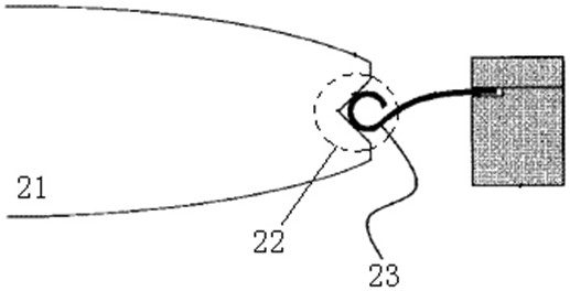
[0035] When the lens 102 changes along the radial direction of the lens 103 due to uneven heating, thereby causing the surface shape of the lens 102 to change, different forces can be applied at different positions of the elastic member 101 to improve the surface shape. like Figure 7 As shown, in this embodiment, four forces f1 , f2 , f3 , f4 are evenly distributed along the circumferential direction on the upper surface of the elastic member 101 as an example for illustration. Before the force is applied, due to the uneven heating of the lens 102, the lens 102 expands, so that the surface shape of the lens 102 is relatively large, and the surface shape is 25nm, such as Figure 8 shown. By adjusting the size of f1-f4, the expansion of the lens 102 in the radial direction is restrained, thereby improving the surface accuracy of the lens 102, and the improved effect is as follows Figure 9 As shown, the surface type reaches 7nm.
[0036] The lens fixing structure proposed by...
PUM
 Abstract
Description
Claims
Application Information
 - R&D Engineer
- R&D Manager
- IP Professional
- Industry Leading Data Capabilities
- Powerful AI technology
- Patent DNA Extraction
Browse by: Latest US Patents, China's latest patents, Technical Efficacy Thesaurus, Application Domain, Technology Topic, Popular Technical Reports.
© 2024 PatSnap. All rights reserved.Legal|Privacy policy|Modern Slavery Act Transparency Statement|Sitemap|About US| Contact US: help@patsnap.com