
A new type of lamp strip molding processing method

A technology for forming and processing light strips, applied in the processing of insulating substrates/layers, printed circuits, electrical components, etc., can solve the problems of high processing costs, low production efficiency, and high processing costs of gong boards, and improve aesthetics. As well as the effect of quality, improved production efficiency, and high machining accuracy

Active Publication Date: 2019-04-12
JIAN MANKUN TECH
View PDF8 Cites 0 Cited by
  • Summary
  • Abstract
  • Description
  • Claims
  • Application Information

AI Technical Summary

Problems solved by technology

Disadvantages: the cost of mold making is expensive; the imposition spacing needs to be ≥1.2mm, which reduces the utilization rate of copper clad laminates and virtually increases the production cost; and the edge of the board is rough after punching and forming, which affects the appearance of the product
Disadvantages: high processing cost and low production efficiency of gong boards; imposition spacing needs to be ≥1.6mm, which reduces the utilization rate of copper clad laminates and virtually increases production costs; dimensional tolerances are affected by tool life and tool wear, and dimensional out-of-tolerance often occurs The problem
[0005] To sum up the above, the punching molding of the lamp strip has the disadvantages of high processing cost and poor product quality; the molding of the lamp strip has the disadvantages of high processing cost, low production efficiency and poor product quality

Method used


Image

  • A new type of lamp strip molding processing method
  • A new type of lamp strip molding processing method
  • A new type of lamp strip molding processing method

Examples


Embodiment Construction

[0027] In order to make the technical means, creative features, goals and effects achieved by the present invention easy to understand, the technical solution of the present invention will be clearly and completely described below.

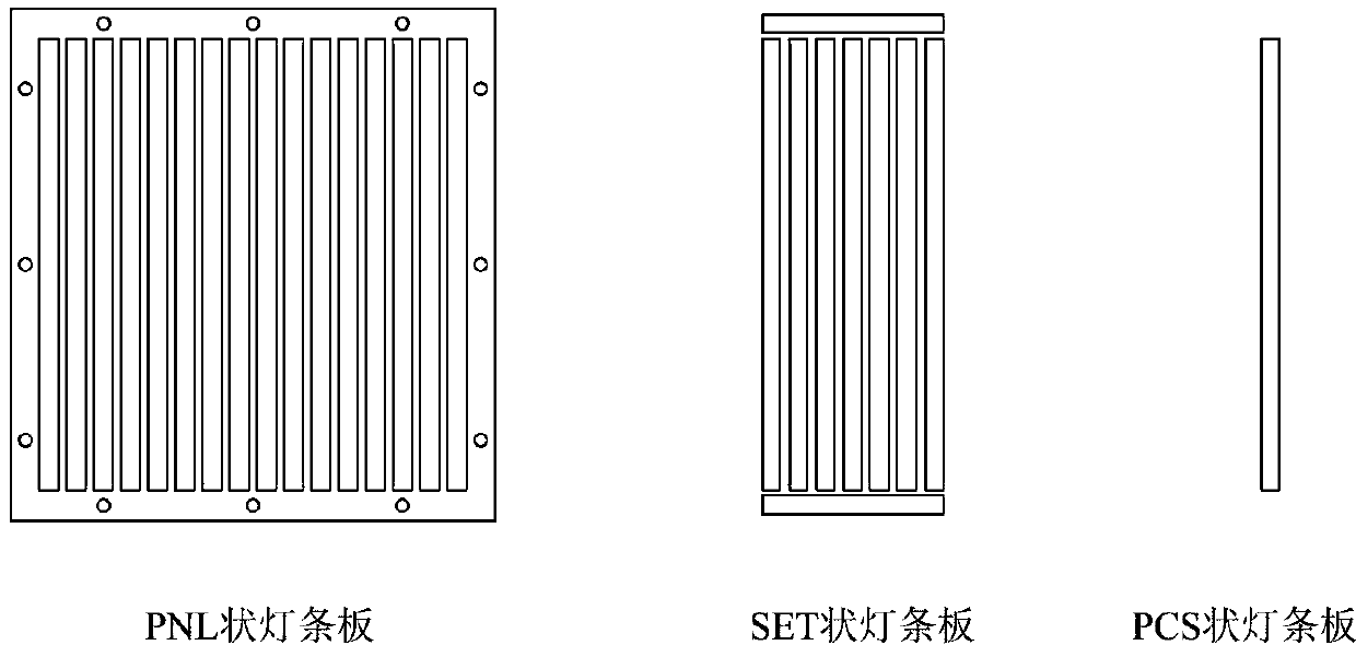
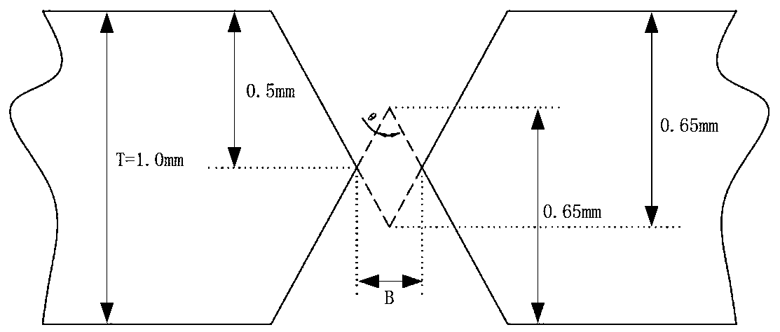
[0028] Take the PNL-shaped light strip with a thickness of 1.0mm as an example, such as figure 1 As shown, the edge width of the PNL-shaped light strip is ≥8.5mm. like image 3 As shown, the V-CUT imposition spacing B=0.2mm. like figure 2 As shown, the V-CUT depth is set to 0.65mm in the design of the V-CUT cut-through section drawing, that is, the V-CUT excess thickness is set to 2.0 / 2-0.3=0.7mm, and the upper and lower knives cut into half the thickness of the light strip and then Add 0.15mm, upper knife V-CUT depth 0.65mm+lower knife V-CUT depth 0.65mm=1.3mm>board thickness 1.0mm, to ensure that the light strip can be cut through. like Figure 4 As shown, take 2 pieces of PNL-shaped light strips, hang the short sides on the PIN pins of th...


PUM


Abstract

The invention discloses a novel light bar panel molding processing method. The method includes the following steps that panel hanging holes are drilled in the panel sides of PNL-shaped light bar panels by means of a numerical control drilling machine; the short sides of the drilled PNL-shaped light bar panels are hung on a numerical control V-CUT machine and fixed, V-grooving is conducted on the short sides, one panel is processed each time, and the V-CUT residual thickness is set to be 0.15 mm so as to bring convenience to subsequent panel dividing; the long sides of the PNL-shaped light bar panels with the short sides obtained after V-CUT are hung on the numerical control V-CUT machine and fixed, V-grooving is conducted on the long sides, two panels are processed each time, and the V-CUT residual thickness is set to be 0.3 mm smaller than half of the total thickness of two stacked PNL-shaped light bar panels; the stacking positions of the two PNL-shaped light bar panels are switched, V-grooving is conducted on the long sides of the PNL-shaped light bar panels again, and the V-CUT residual thickness is set to be 0.3 mm smaller than half of the total thickness of two stacked PNL-shaped light bar panels; by means of a panel dividing machine or manual panel dividing, the short sides of the PNL-shaped light bar panels are cut off, then the PNL-shaped light bar panels are composed into SET-shaped light bar panels or PCS-shaped light bar panels, and V-CUT molding of the light bar panels is completed. The method saves the light bar panel processing cost and improves production efficiency and product quality.

Description

technical field [0001] The invention belongs to the technical field of light strip processing technology, and in particular relates to a novel light strip forming and processing method. Background technique [0002] A light strip is a printed circuit board used in LED lights and TV backlights. With the advancement of modern technology, TVs are becoming thinner and wider, which means that the light strips will become thinner and longer. [0003] There are mainly two methods of forming traditional light strips: punching and gongs. Punching board forming: Step 1, use a CNC drilling machine to drill a number of positioning holes on the edge of the PNL-shaped light strip board (hereinafter referred to as PNL board); Step 2, Hang the PNL board on the PIN pin of the mold; Step 3, Start the punching machine, use The knife edge on the mold punches the PNL board into SET-shaped light strips (hereinafter referred to as SET boards) or PCS-shaped light strips (hereinafter referred to a...

Claims


Application Information

Patent Timeline
Patent Type & Authority Patents(China)
IPC IPC(8): H05K3/00
CPCH05K3/0052
Inventor 张孝斌王小亮
Owner JIAN MANKUN TECH
Learn More