
Power supply system and power supply control method

A power supply system and electric power technology, applied in the field of electric power, can solve problems such as complicated operation, difficult implementation, and easy damage

Active Publication Date: 2017-06-13
北京东方华氢科技有限公司
View PDF5 Cites 9 Cited by
  • Summary
  • Abstract
  • Description
  • Claims
  • Application Information

AI Technical Summary

Problems solved by technology

This type of battery has the advantages of high conversion efficiency, large capacity, high specific energy, wide power range, and no charging, but due to high cost and complicated system, it is limited to some special purposes, such as spaceships, submarines, military, TV transfer stations, Lighthouses and buoys etc.
Usually this type of battery generates electric current through the discharge reaction of the stack. When the battery is turned off, that is, when the stack is turned off, because hydrogen and liquid water still remain inside, in order to avoid its continued reaction to generate electric energy, in the prior art Usually, nitrogen gas is injected into the stack to discharge hydrogen and liquid water, but this method has large limitations and is difficult to implement
In addition, hydrogen-oxygen fuel cells in the prior art do not have a relatively strict monitoring process for the introduction of hydrogen and oxygen (air), which leads to poor performance of the discharge reaction in the stack.
[0009] 3. At present, due to changes in the load on the power line or changes in power consumption, the voltage on the power line usually changes. In order to provide stable voltage on the power line, the current method is to provide power modules such as storage batteries. Supplementary power voltage, but due to the frequent charging and discharging of the storage battery, it is easily damaged and the service life will be affected
Therefore, regular replacement is usually required, which not only brings a burden on cost, but also has the characteristics of complicated operation.

Method used


Image

  • Power supply system and power supply control method
  • Power supply system and power supply control method
  • Power supply system and power supply control method

Examples


Embodiment Construction

[0109] The present invention will be described in detail below in conjunction with the accompanying drawings.

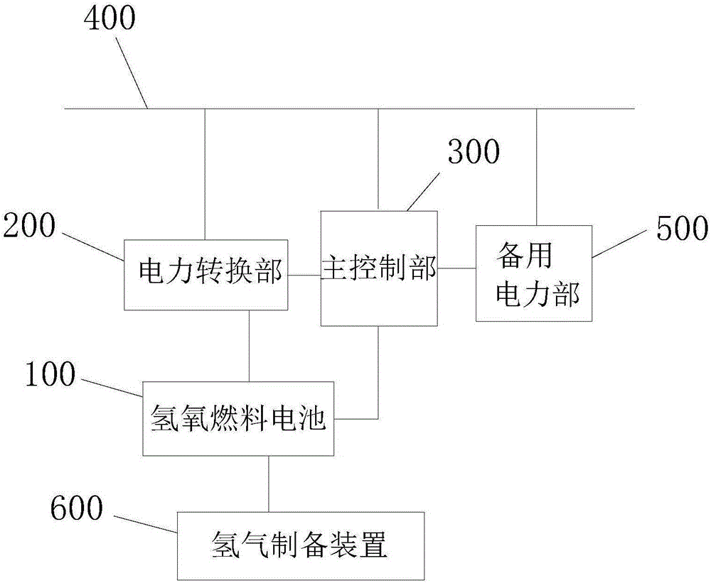
[0110] Such as figure 1 As shown, the present invention provides a power supply system, which includes:

[0111] A hydrogen production device, which utilizes liquid methanol to produce hydrogen;

[0112] A hydrogen-oxygen fuel cell connected to the hydrogen production device for receiving hydrogen and generating first electricity; and

[0113] The power conversion device is connected with the fuel cell for receiving the first power and converting it into the second power and supplying it to the power line, so as to provide a normal working voltage for the load on the power line.

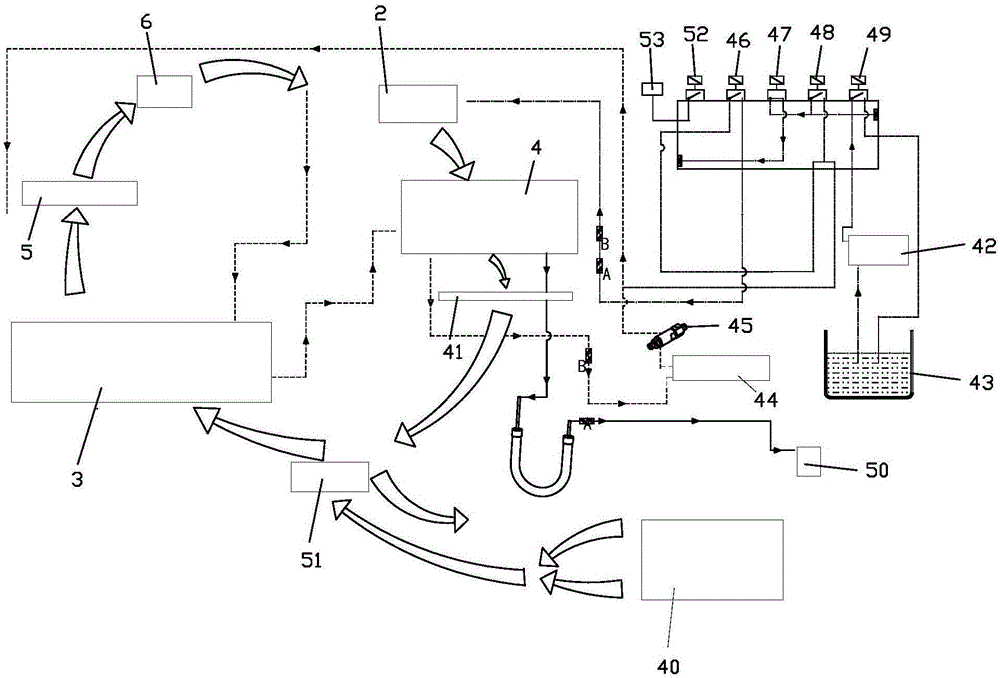
[0114] Such as figure 2 As shown, the hydrogen production device includes:

[0115] The base shell 1 is provided with an air inlet and an air outlet;

[0116] An evaporator 2, which is arranged in the base shell 1 for converting methanol from a liquid state to a gaseous state;

[011...


PUM


Abstract

The invention provides a power supply system and a power supply control method. The power supply system comprises a hydrogen gas preparation device, a hydrogen-oxygen fuel battery and a power control device, wherein the hydrogen gas preparation device prepares hydrogen gas from liquid methanol; the hydrogen-oxygen fuel battery is connected with the hydrogen gas preparation device and is used for receiving the hydrogen gas and generating first power; and the power control device is connected with the hydrogen-oxygen fuel battery, and is used for converting the first power into second power before supplying onto a power line and simultaneously controlling the power generation operation of the hydrogen-oxygen fuel battery according to the voltage on the power line. The power supply system provided by the invention is low in cost and can prepare hydrogen gas at a high efficiency, so that the fuel battery can continuously provide supplementary power voltage required on the power line.

Description

technical field [0001] The invention relates to the field of electric power, in particular to a power supply system and a control method for power supply. Background technique [0002] 1. Hydrogen is used frequently in industry. In the prior art, there are multiple methods for the industrial preparation of hydrogen: [0003] ①The electrolysis method electrolyzes water to obtain hydrogen and oxygen. The chlor-alkali industry electrolyzes salt solution to produce chlorine gas and caustic soda, and also produces hydrogen as a by-product. The electrolysis method can obtain pure hydrogen, but the power consumption is very high, and every 1m of hydrogen produced 3 , power consumption of 21.6 ~ 25.2MJ. [0004] ② Hydrocarbon cracking method The cracked gas obtained by this method contains a large amount of hydrogen, and the hydrogen content varies depending on the nature of the raw material and the cracking conditions. Hydrogen with a purity of 90% can be obtained by cryogenic...

Claims


Application Information

Patent Timeline
Patent Type & Authority Applications(China)
IPC IPC(8): H01M8/04H02J7/00H01M8/04014
CPCH01M8/04089H01M8/04201H01M8/04537H01M8/04544H02J7/00H02J7/007Y02E60/50
Inventor 冀中华彭伟
Owner 北京东方华氢科技有限公司
Learn More