Voltage-resistant terminal ring structure and power device

A technology of terminal rings and pressure-resistant rings, which is applied to semiconductor devices, electrical components, circuits, etc., and can solve problems such as unstable breakdown voltage

Active Publication Date: 2017-06-13
LEADING ENERGY BEIJING ELECTRONICS TECH CO LTD
View PDF4 Cites 1 Cited by
  • Summary
  • Abstract
  • Description
  • Claims
  • Application Information

AI Technical Summary

Problems solved by technology

[0007] The main purpose of this application is to provide a voltage-resistant terminal ring structure and...

Method used


Image

  • Voltage-resistant terminal ring structure and power device
  • Voltage-resistant terminal ring structure and power device
  • Voltage-resistant terminal ring structure and power device

Examples


Embodiment

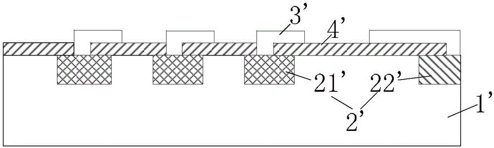
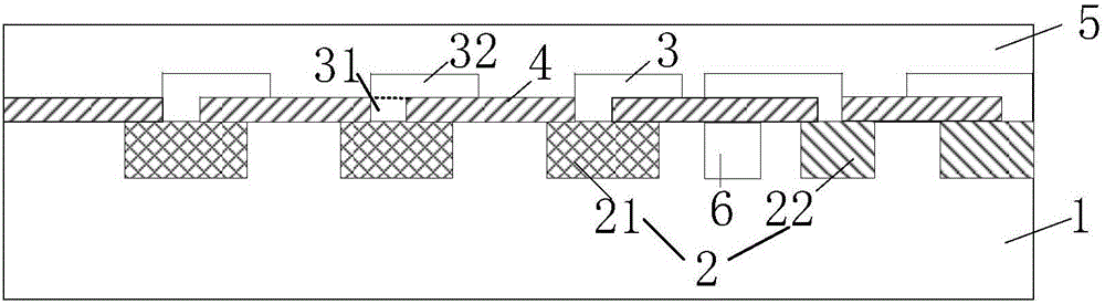
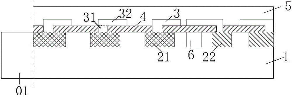
[0047] The specific structure of the pressure-resistant terminal ring is as follows: figure 2 As shown, compared with the structure in the prior art, this structure adds an equipotential ring and its corresponding metal field plate. Among them, the substrate 1 is an N-type silicon doped region, the withstand voltage ring 21, the additional ion implantation region 6 and the equipotential ring 22 are all heavily doped P-type regions, the dielectric film 4 is a silicon dioxide layer, and the field plate 3 Both are metal field plates of aluminum silicon copper, and the passivation film 5 is a silicon nitride film.

[0048] When the device is reverse-biased, the potential of the field plate corresponding to the withstand voltage ring is "negative", and the potential of the substrate directly below it is "positive". The potential of the field plate corresponding to the equipotential ring is "positive". The potential of the substrate directly below is "negative", so that the movabl...


PUM


Abstract

The invention provides a voltage-resistant terminal ring structure and a power device. The voltage-resistant terminal ring structure comprises a substrate, multiple field rings, multiple field plates, dielectric films and at least one additional ion injection area; the field rings are arranged on the portion, close to a second surface, in the substrate at intervals, the conduction type of the field rings is opposite to that of the substrate, the field rings comprise at least one voltage-resistant ring and two equipotential rings, and the two equipotential rings are sequentially arranged in the direction far away from the voltage-resistant rings; the field plates and the field rings are arranged in a one-to-one corresponding mode, parallel segments corresponding to the voltage-resistant rings extend in the direction close to a third surface, and parallel segments corresponding to the equipotential rings extend in the direction far away from the third surface; the dielectric films are arranged on a second part surface and part of a first part surface; the additional ion injection areas are arranged on the portions, between the adjacent voltage-resistant rings and equipotential rings, of the substrate, and the conduction type of the additional ion injection areas is opposite to that of the substrate. The reverse breakdown voltage of the power device with the structure is stable.

Description

technical field [0001] The present application relates to the field of semiconductors, in particular, to a voltage-resistant terminal ring structure and a power device. Background technique [0002] With the development of power electronics technology, high-voltage power devices have become the core components in power electronics applications. [0003] figure 1 Shown is a typical existing voltage-resistant terminal ring structure of a high-voltage power device. It consists of a substrate 1', an internal field ring 2', a field plate 3' and a dielectric film 4', wherein the field ring 2' is composed of a pressure-resistant ring 21' and a stop ring 22' (equal potential ring, also known as the equipotential ring), this structure has very high requirements on the product manufacturing process, and is very sensitive to the charge existing in the product manufacturing process. That is to say, once mobile charges are introduced for any reason during processing, the breakdown vol...

Claims


Application Information

Patent Timeline
IPC IPC(8): H01L29/06
CPCH01L29/0615
Inventor 义夫华国安
Owner LEADING ENERGY BEIJING ELECTRONICS TECH CO LTD
Why Eureka
Try Eureka