Filling device for vacuum system and filling method of enclosed cavity

A vacuum system and cavity technology, applied in lighting and heating equipment, indirect heat exchangers, etc., can solve problems such as difficult to control the quantity of heat pipe working medium, clean non-condensable gas, and difficult to ensure the working performance of heat pipes, etc., to achieve Convenient and quick vacuuming and filling effect

Inactive Publication Date: 2017-06-13
湖南中科泰通热能科技发展有限公司
View PDF6 Cites 0 Cited by
  • Summary
  • Abstract
  • Description
  • Claims
  • Application Information

AI Technical Summary

Problems solved by technology

However, in the production process of the heat pipe, it needs to be vacuumized and sealed after filling the working fluid. The existing heat pipe filling methods include the liquid injection vacuum method and the vacuum injection liquid injection method. It is difficult to remove the non-condensable gas, and it is difficult to control the amount of working fluid in the heat pipe, so it is difficult to ensure the working performance of the heat pipe
The vacuum injection method can well overcome the above technical defects, but the sealing interface and its filling method have disadvantages such as complicated operation and short sealing life.

Method used


Image

  • Filling device for vacuum system and filling method of enclosed cavity
  • Filling device for vacuum system and filling method of enclosed cavity

Examples


Embodiment Construction

[0016] In order to make the objectives, technical solutions and advantages of the present invention clearer, the technical solutions in the embodiments of the present invention will be described in more detail below in conjunction with the drawings in the embodiments of the present invention. In the drawings, the same or similar reference numerals denote the same or similar elements or elements having the same or similar functions throughout. Embodiments of the present invention will be described in detail below in conjunction with the accompanying drawings.

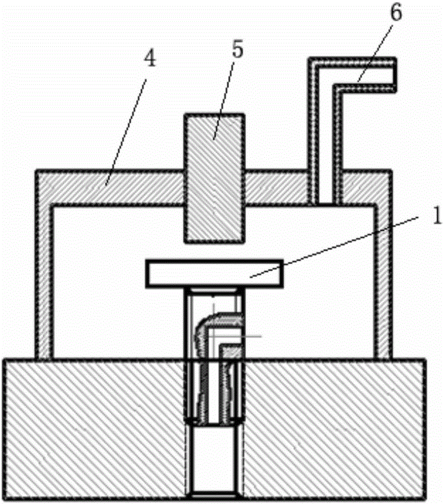
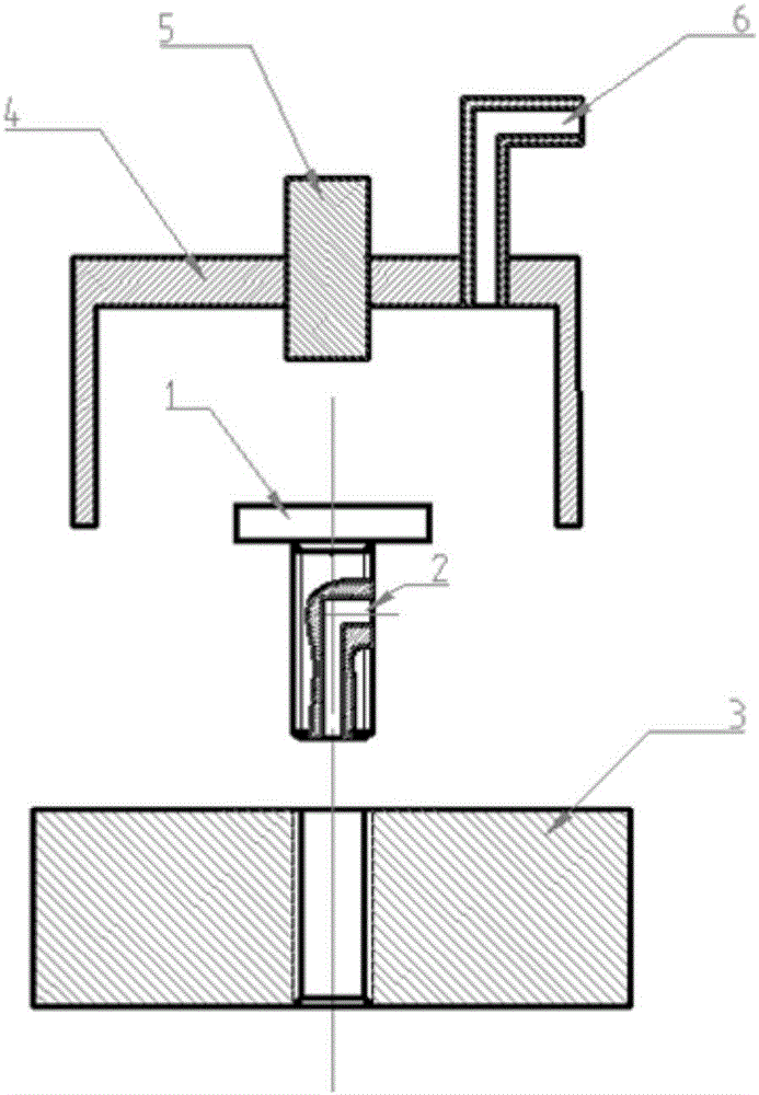
[0017] Such as figure 1 , 2 As shown, a filling device for a vacuum system, including a screw 1 with a filling channel, a cover 4 with a suction filling port 6, and a fastener for rotating the screw arranged on the cover 4 5. One end of the filling channel 2 in the screw 1 is opened on the bottom of the screw, and the other end is opened on the side of the screw. There is an internal thread matching the screw on the ca...


PUM


Abstract

A filling device for a vacuum system and a filling method for a closed cavity, including a screw with a filling channel, a cover with a suction filling port, and a fastening screw for rotating the screw provided on the cover One end opening of the filling channel in the screw is set on the bottom of the screw, the other end opening is set on the side of the screw, and a cavity with an internal thread matching the screw is provided on the cavity that needs to be vacuumed. The screw is sealed and installed on the interface, and the cover is sealed and installed on the outside of the interface, so that a sealed space is formed in the cover, and the fastener on the cover is tightly connected with the cover and the fastener can The cover body rotates while moving up and down, the fasteners correspond to the positions of the screws, and the screws are screwed out or screwed into the interface through the fasteners. The invention is a filling device for a vacuum system with simple structure and convenient operation, simple processing and operation, and effectively solves the problems of filling and sealing.

Description

technical field [0001] The invention relates to a filling device for a vacuum system and a filling method for a closed cavity. Background technique [0002] Heat pipes that utilize the vapor-liquid phase transition characteristics of working fluids for heat transfer are high-performance heat transfer elements that can be widely used in various fields of national production, such as heat dissipation of power electronic equipment, waste heat recovery, etc. However, in the production process of the heat pipe, it needs to be vacuumized and sealed after filling the working fluid. The existing heat pipe filling methods include the liquid injection vacuum method and the vacuum liquid injection method. Because the liquid injection vacuum method is very It is difficult to remove the non-condensable gas, and it is difficult to control the amount of working fluid in the heat pipe, so it is difficult to ensure the working performance of the heat pipe. The vacuum pumping liquid injectio...

Claims


Application Information

Patent Timeline
Patent Type & Authority Applications(China)
IPC IPC(8): F28D15/02
CPCF28D15/0283
Inventor 唐大伟
Owner 湖南中科泰通热能科技发展有限公司
Why Eureka
Try Eureka