An AC Electromagnetically Driven Abrasive Slurry Jet Supercharging Device

An abrasive slurry jet and electromagnetic drive technology, which is applied in the direction of abrasive feeding device, used abrasive processing device, abrasive, etc., can solve the problem that the positive arc-shaped platinum-plated electrode plate and the negative arc-shaped platinum-plated electrode cannot be guaranteed. Plate electric field strength and electric field uniformity, the electrode density of the electrode plate cannot be increased, and the energy loss cannot be sufficiently reduced to achieve the effects of simple structure, reduced energy loss, and convenient operation

Active Publication Date: 2018-12-11
ANHUI UNIV OF SCI & TECH
View PDF5 Cites 0 Cited by
  • Summary
  • Abstract
  • Description
  • Claims
  • Application Information

AI Technical Summary

Problems solved by technology

[0003] However, the existing electromagnetic abrasive slurry jet device uses permanent magnets as the magnetic source, which cannot provide high magnetic field strength, and the pressure head forming the jet is relatively small, so the generated power can only be calculated by the height of the lifting liquid, which cannot Avoid the phenomenon that the electromagnetic is difficult to drive the electromagnetically driven abrasive slurry to form a jet. Some electromagnetic abrasive slurry jet devices cannot increase the electrode density of the electrode plate, and cannot guarantee the electric field between the positive arc-shaped platinum-plated electrode plate and the negative arc-shaped platinum-plated electrode plate. Intensity and uniformity of the electric field, and some electromagnetic abrasive slurry jet devices cannot guarantee that the direction of the ampere force is the same as the direction of the outlet of the flow channel, and cannot fully reduce the energy loss of the electromagnetically driven abrasive slurry to form a jet

Method used


Image

  • An AC Electromagnetically Driven Abrasive Slurry Jet Supercharging Device
  • An AC Electromagnetically Driven Abrasive Slurry Jet Supercharging Device
  • An AC Electromagnetically Driven Abrasive Slurry Jet Supercharging Device

Examples


Embodiment Construction

[0019] In order to make the technical means, creative features, objectives and effects achieved by the present invention easy to understand, the present invention will be further described below in conjunction with specific embodiments and illustrations.

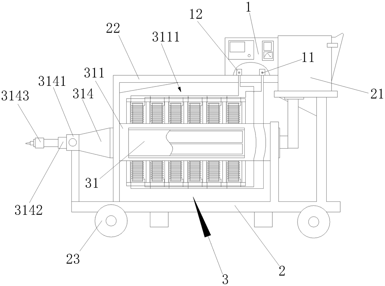
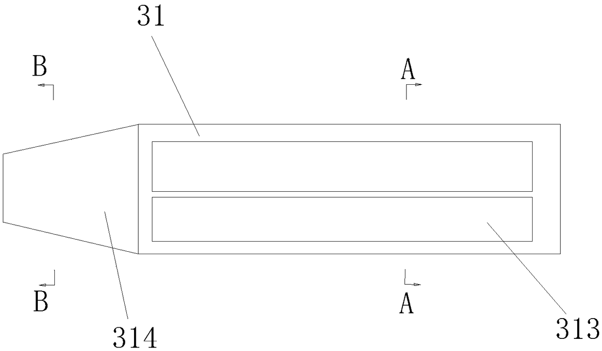
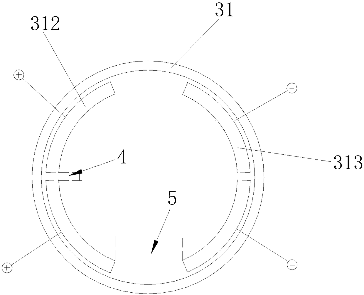
[0020] Such as figure 1 , figure 2 , image 3 and Figure 4 As shown, the ac type electromagnetically driven abrasive slurry jet supercharging device includes an ac control box 1 and a moving frame 2, the lower end of the ac control box 1 is equipped with a positive terminal block 11 and a negative terminal block 12, and Comprising an orthogonal electromagnetic field driving device 3, the orthogonal electromagnetic field driving device 3 includes a circular cross-section flow channel 31, a nylon square frame 311 is installed on the outside of the circular cross-section flow channel 31, and the upper side of the nylon square frame 311 and the underside of the nylon square frame 311 are equipped with a energized coil row 3...


PUM


Abstract

The invention discloses an alternating current type electromagnetic driving adhesive slurry jet flow pressurizing device which comprises an alternating current electric control box and a mobile rack and also comprises an orthogonal electromagnetic field driving device, wherein the orthogonal electromagnetic field driving device comprises a round circular cross runner; a nylon square frame is mounted on the outer side of the round circular cross runner; electrified wire ring rows are mounted on the upper side of the nylon square frame and the lower side of the nylon square frame; positive arc-shaped platinum plating electrode plates and negative arc-shaped platinum plating electrode plates are symmetrically mounted on the inner side of the round circular cross runner; small gaps are formed between the adjacent positive arc-shaped platinum plating electrode plates and the adjacent negative arc-shaped platinum plating electrode plates; and large gaps are formed between the positive arc-shaped platinum plating electrode plates and the negative arc-shaped platinum plating electrode plates. The device disclosed by the invention can effectively improve the magnetic field intensity and increase the electrode density of the electrode plates, so that the electric field intensity and electric field uniformity between the positive arc-shaped platinum plating electrode plates and the negative arc-shaped platinum plating electrode plates is ensured, and the electric field and the magnetic field are orthogonally arranged.

Description

technical field [0001] The invention relates to the technical field of abrasive water jet mechanical equipment design, in particular to an AC electromagnetically driven abrasive slurry jet supercharging device. Background technique [0002] The water jet is a high-speed water stream of different shapes formed by the nozzle, and the flow rate of the jet depends on the pressure drop before and after the nozzle outlet section. Water jetting is the simplest form of energy transformation and application. Usually, the power-driven pump completes a suction and discharge process of water, pumps a certain amount of water to the high-pressure pipeline, and makes it reach the nozzle with a certain amount of energy. The hole diameter of the nozzle is required to be much smaller than that of the high-pressure pipeline, so this certain amount of water reaching the nozzle must be accelerated if it wants to flow out of the nozzle hole. In this way, the water that accelerates condensation ...

Claims


Application Information

Patent Timeline
Patent Type & Authority Patents(China)
IPC IPC(8): B24C7/00B24C9/00
CPCB24C7/0007B24C9/00
Inventor 谢淮北王岩王从东
Owner ANHUI UNIV OF SCI & TECH
Why Eureka
Try Eureka