A machining method for a head-cone hat-shaped integral FRP cabin section with an angled end face
A mechanical processing and glass fiber reinforced plastics technology, applied in metal processing equipment, metal processing mechanical parts, manufacturing tools, etc., can solve the problems of difficult alignment of clamping, difficult to determine positioning datum, difficult to guarantee the relative butt size of the end face, etc. Clamp alignment is difficult, realize conversion, easy to clamp alignment effect
- Summary
- Abstract
- Description
- Claims
- Application Information
AI Technical Summary
Problems solved by technology
Method used
Image
Examples
Embodiment 1
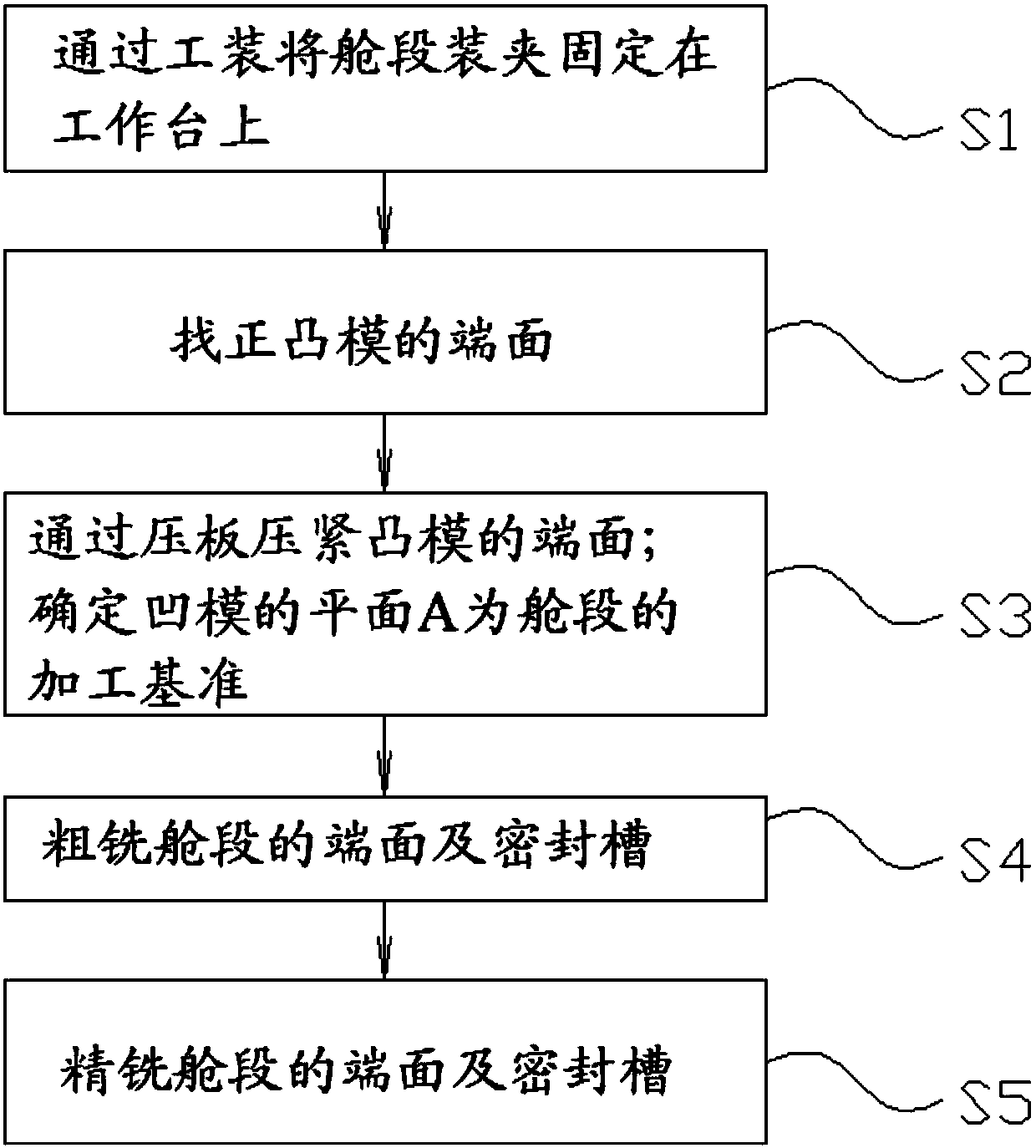
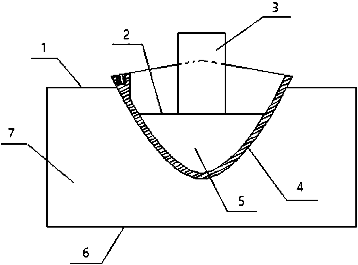
[0033] S1: Clamp and fix the cabin section 4 on the workbench through the tooling; the tooling includes: the die 7 and the punch 5; the die 7 is a cuboid with grooves on the top surface (plane A); the bottom surface of the die 7 is a plane B6; the surface of the groove matches the outer surface of the cabin section 4. The outer surface of the punch 5 matches the inner surface of the cabin section 4; the end surface of the punch 5 is plane C2; the plane B6 of the die 7 is pressed on the workbench; the outer surface of the cabin section 4 is pressed on the die 7 On the surface of the groove;
[0034] S2: Align the end face of punch 5.
[0035] S3: pressing the end face of the punch 5 by the pressing plate 3; determining the plane A1 of the die 7 as the processing reference of the cabin section 4.
[0036] S4: rough milling the end face and sealing groove of cabin section 4.
[0037] S5: The end face and sealing groove of fine milling cabin section 4; during the process of f...
Embodiment 2
[0039] S1: Clamp and fix the cabin section 4 on the workbench through the tooling; the tooling includes: the die 7 and the punch 5; the die 7 is a cuboid with grooves on the top surface (plane A); the bottom surface of the die 7 is a plane B6; the surface of the groove matches the outer surface of the cabin section 4. The outer surface of the punch 5 matches the inner surface of the cabin section 4; the end surface of the punch 5 is plane C2; the plane B6 of the die 7 is pressed on the workbench; the outer surface of the cabin section 4 is pressed on the die 7 On the surface of the groove;
[0040] S2: Align the end face of punch 5.
[0041] S3: pressing the end face of the punch 5 by the pressing plate 3; determining the plane A1 of the die 7 as the processing reference of the cabin section 4.
[0042] S4: rough milling the end face and sealing groove of cabin section 4.
[0043] S5: The end face and sealing groove of fine milling cabin section 4; during the process of f...
Embodiment 3
[0045]S1: Clamp and fix the cabin section 4 on the workbench through the tooling; the tooling includes: the die 7 and the punch 5; the die 7 is a cuboid with grooves on the top surface (plane A); the bottom surface of the die 7 is a plane B6; the surface of the groove matches the outer surface of the cabin section 4. The outer surface of the punch 5 matches the inner surface of the cabin section 4; the end surface of the punch 5 is plane C2; the plane B6 of the die 7 is pressed on the workbench; the outer surface of the cabin section 4 is pressed on the die 7 On the surface of the groove;
[0046] S2: Align the end face of punch 5.
[0047] S3: pressing the end face of the punch 5 by the pressing plate 3; determining the plane A1 of the die 7 as the processing reference of the cabin section 4.
[0048] S4: rough milling the end face and sealing groove of cabin section 4.
[0049] S5: The end face and sealing groove of fine milling cabin section 4; during the process of fi...
PUM
 Abstract
Description
Claims
Application Information
 - R&D Engineer
- R&D Manager
- IP Professional
- Industry Leading Data Capabilities
- Powerful AI technology
- Patent DNA Extraction
Browse by: Latest US Patents, China's latest patents, Technical Efficacy Thesaurus, Application Domain, Technology Topic, Popular Technical Reports.
© 2024 PatSnap. All rights reserved.Legal|Privacy policy|Modern Slavery Act Transparency Statement|Sitemap|About US| Contact US: help@patsnap.com


