
Motor shaft fully automatic polishing machine

A fully automatic, polishing machine technology, applied in grinding/polishing equipment, grinding frame, grinding feed motion, etc., can solve the problems of low processing efficiency, low degree of automation, reduced processing efficiency, etc., and achieve processing efficiency High, high degree of automation, the effect of improving grinding accuracy and efficiency

Active Publication Date: 2017-06-09
江苏瑞鑫数控装备有限公司
View PDF5 Cites 9 Cited by
  • Summary
  • Abstract
  • Description
  • Claims
  • Application Information

AI Technical Summary

Problems solved by technology

[0002] With the progress and development of society and the advancement of science and technology, there are more and more types of mechanical equipment with more and more powerful functions. Correspondingly, the more powerful mechanical equipment has higher requirements for the dimensional accuracy of mechanical parts, bearings as Indispensable parts in industrial machinery play a very important role in the function, life and machining accuracy of mechanical equipment. Therefore, people have higher and higher requirements for bearing precision, and the existing polishing machine for superfinishing of bearing The structure is simple, the degree of automation is low, the polishing effect is poor, and the processing efficiency is low, which increases the labor intensity of workers, reduces the processing efficiency, and increases energy consumption

Method used


Image

  • Motor shaft fully automatic polishing machine
  • Motor shaft fully automatic polishing machine
  • Motor shaft fully automatic polishing machine

Examples


Embodiment Construction

[0035] In order to enable those skilled in the art to better understand the technical solution of the present invention, the present invention will be described in detail below in conjunction with the accompanying drawings. The description in this part is only exemplary and explanatory, and should not have any limiting effect on the protection scope of the present invention. .

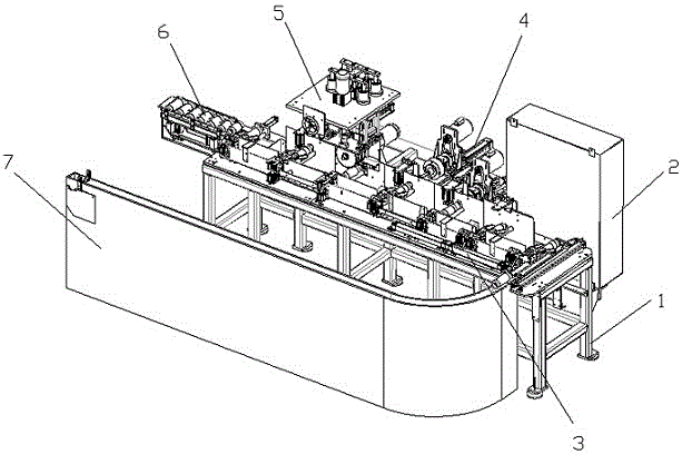
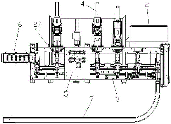
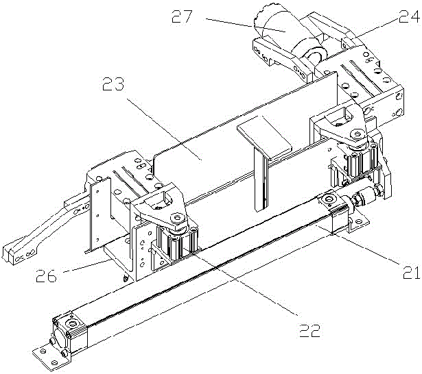
[0036] Such as Figure 1-Figure 9 As shown, the structural connection relationship of the present invention is: a kind of motor shaft automatic polishing machine, it comprises frame 1, and described frame 1 front is provided with feeding conveyor 7 and is connected with feeding device 3 on frame 1 table top ; The array on the feeding device 3 is provided with a manipulator 24 for clamping the processed parts 27; the inner circle grinding device 4 is provided directly behind the manipulator 24, and the outer circle grinding device 5 is provided directly above; the frame 1 side The side is provided with...


PUM


Abstract

The invention discloses a motor shaft fully automatic polishing machine, which comprises a machine frame, wherein a material feeding conveying machine is arranged in front of the machine frame and is connected with a material conveying device arranged on a machine frame table top; a mechanical hand used for clamping processing parts is arranged on the material conveying device in an array way; an inner circle grinding device is arranged right behind the mechanical hand; an outer circle grinding device is arranged right above the mechanical hand; a discharging device is arranged at the side edge of the machine frame; the material conveying device comprises a mechanical hand, a connecting plate and a feeding big air cylinder; the inner circle grinding device comprises a telescopic air cylinder, a first motor and a cutter rotating rod, the outer circle grinding device comprises a grinding wheel, a second motor, a movable frame, a fixed frame, a feeding motor and a height air cylinder; the discharging device comprises a fixed recessed plate and a movable recessed plate; the bottom of the movable recessed plate is connected with an upper pushing air cylinder; the upper pushing air cylinder is connected with a lateral pushing air cylinder. The motor shaft fully automatic polishing machine has the advantages that the mass fully automatic polishing on the motor shaft can be realized; the polishing precision is high; the efficiency is high; the processing precision of a bearing can be greatly improved; the processing speed of the bearing can be greatly accelerated.

Description

technical field [0001] The invention relates to the technical field of polishing equipment, in particular to a fully automatic motor shaft polishing machine. Background technique [0002] With the progress and development of society and the advancement of science and technology, there are more and more types of mechanical equipment with more and more powerful functions. Correspondingly, the more powerful mechanical equipment has higher requirements for the dimensional accuracy of mechanical parts, bearings as Indispensable parts in industrial machinery play a very important role in the function, life and machining accuracy of mechanical equipment. Therefore, people have higher and higher requirements for bearing precision. However, the existing polishing machine for superfinishing of bearings The structure is simple, the degree of automation is low, the polishing effect is poor, and the processing efficiency is low, which increases the labor intensity of workers, reduces the...

Claims


Application Information

Patent Timeline
IPC IPC(8): B24B27/00B24B41/00B24B41/06B24B47/20B24B41/02B24B5/12
CPCB24B5/12B24B27/0023B24B27/0069B24B27/0076B24B27/0092B24B41/005B24B41/02B24B41/06B24B47/20
Inventor 不公告发明人
Owner 江苏瑞鑫数控装备有限公司
Learn More