
Line-of-sight path identification method in indoor environment based on channel state information

A path recognition and indoor environment technology, applied in the field of situation awareness, can solve problems such as complex recognition process, environmental interference, and poor recognition robustness, and achieve the effects of reducing overhead, overcoming poor time stability, and superior line-of-sight detection effect

Inactive Publication Date: 2017-05-31
NANJING UNIV OF POSTS & TELECOMM
View PDF5 Cites 40 Cited by
  • Summary
  • Abstract
  • Description
  • Claims
  • Application Information

AI Technical Summary

Problems solved by technology

At present, the problem of line-of-sight path recognition technology is that the recognition process is complicated
This invention can optimize the indoor positioning problem of wireless LAN to a certain extent, improve positioning accuracy, and eliminate positioning errors caused by multipath and non-line-of-sight in complex indoor environments, but the identification process is complicated
In addition, the existing line-of-sight path identification methods are mainly based on signal reception strength, but there are factors such as environmental interference, and the identification robustness is poor.

Method used


Image

  • Line-of-sight path identification method in indoor environment based on channel state information
  • Line-of-sight path identification method in indoor environment based on channel state information
  • Line-of-sight path identification method in indoor environment based on channel state information

Examples


Embodiment Construction

[0030] The specific embodiment of the present invention will be further described in detail in conjunction with the accompanying drawings.

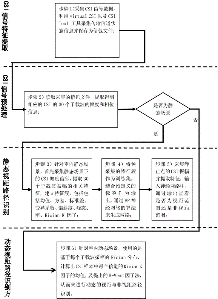
[0031] figure 1 is a schematic diagram of a line-of-sight path and a non-line-of-sight path in an indoor environment, where RT corresponds to a line-of-sight path with AP1, and RT' corresponds to a non-line-of-sight path with AP1; figure 2 The flowchart of indoor line-of-sight path recognition scheme based on CSI is given. The specific embodiment of the present invention will be further described in detail in conjunction with the accompanying drawings. The purpose of the invention is to realize the recognition of sight distance and non-line-of-sight in indoor dynamic and static environments. The working principle is to use the physical layer channel state information (CSI) to replace the traditional received signal indication strength information (RSSI). Using CSI information has good time stability, strong resistance to dynamic enviro...


PUM


Abstract

The invention discloses a line-of-sight path identification method in an indoor environment based on channel state information (CSI). The method comprises the following steps: at a CSI signal collection stage, extracting amplitude information of CSI from a signal packet; dividing indoor scenes into a static scene and a dynamic scene; in the static scene, extracting a mean, a variance, a standard deviation, a variation coefficient, a degree of skewness, a kurtosis, a moment and Rician K factors to form a characteristic cluster, then using the characteristic cluster as a training set of a BP neural network, generating the corresponding BP neural network through a pre-defined label, directly extracting the corresponding characteristic cluster from a newly collected static point, inputting the characteristic cluster into a network, and realizing static line-of-sight path identification; and in the dynamic scene, calculating the mean of the Rician K factors of each channel in a CSI sample by using Rician distribution based on the amplitude of each subcarrier, and performing dynamic line-of-sight and non-line-of-sight path identification. By adoption of the line-of-sight path identification method disclosed by the invention, the accuracy of static and dynamic line-of-sight path identification in the indoor environment can be improved, and indoor comprehensive identification of the line-of-sight range can be realized at the same time.

Description

technical field [0001] The invention belongs to the field of scene awareness for locating users or terminals in wireless communication networks, and in particular relates to a line-of-sight path identification method suitable for indoor environments, so as to identify line-of-sight paths under dynamic and static conditions indoors. Background technique [0002] At present, with the rapid development of wireless communication technology, especially driven by the popularity of mobile smart terminals, WLAN (Wireless Local Area Network, WLAN) has become very popular. In homes, shopping malls, airports and other places, WLAN signals are everywhere visible. These large numbers of WLAN infrastructures that have been installed and deployed have laid a physical foundation for the research of WiFi situational awareness. [0003] Perception technologies based on WiFi signals mainly include indoor positioning, personnel detection, motion recognition, and wall-penetrating recognition. ...

Claims


Application Information

Patent Timeline
Patent Type & Authority Applications(China)
IPC IPC(8): H04W24/02H04W84/12H04B17/309
CPCH04W24/02H04W84/12H04B17/309
Inventor 肖甫郭政鑫谢晓辉朱海陈静孙力娟王汝传
Owner NANJING UNIV OF POSTS & TELECOMM
Learn More