A method for treating low-medium radioactive waste
A low-radioactive, waste treatment technology, applied in radioactive purification, nuclear engineering and other directions, can solve the problem of occupying large nuclear waste yard space and other problems, achieve good economic benefits, good curing effect, and broad market prospects.
- Summary
- Abstract
- Description
- Claims
- Application Information
AI Technical Summary
Problems solved by technology
Method used
Image
Examples
Embodiment 1
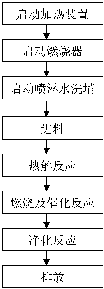
[0030] The specific process steps of the medium and low radioactive waste treatment method involved in this embodiment are:
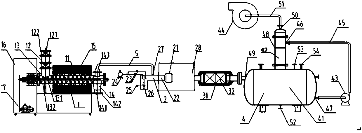
[0031] (1) Start the heating device 11: start the heating device 11 of the pyrolysis reactor 1, and set the temperature of the first temperature controller 16 to be 300-600° C.;
[0032] (2) Start the burner 2: start the automatic fuel circuit oil pump 24, open the two-stage solenoid valve 23 to automatically ignite and burn sequentially, when the fuel part of the burner burns stably, keep the temperature of the combustion chamber 28 at 800-1300°C, pyrolysis The gas enters the burner 2 for combustion, that is, the burner 2 is sprayed and atomized by the middle part, and the automatic fuel circuit oil pump 24 is used to adjust the amount of fuel, and the servo motor 25 adjusts the air inlet 26 to ensure that the pyrolysis gas is fully burned;
[0033] (3) Start the spray water washing tower 3: start the circulating water pump 43 and the induced draft fan...
Embodiment 2
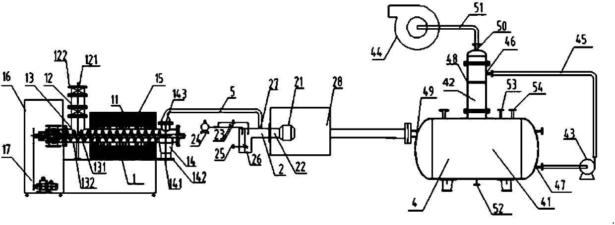
[0044] The difference between this embodiment and Embodiment 1 is that in step (4), the step of adding solid catalyst 32 is omitted, and medium and low radioactive waste is sent into the closed feed system 12 through the feed port 121, and the sealed feed valve 122 is closed; The difference between the device used in the medium and low radioactive waste treatment method involved in the embodiment and the device used in embodiment 1 is that the structure of the catalytic converter 3 is omitted, and the output end of the burner 2 is washed with the spray water through the high temperature resistant pipeline 5 The second gas inlet 49 of the tower 4 is connected.
Embodiment 3
[0046]The difference between this embodiment and Embodiment 1 lies in step (2), before starting the burner 2, open the control valve 61 of the exhaust gas outlet of the burner 2, realize heat exchange between the exhaust gas of the burner 2 and the inlet gas, and increase the temperature of the inlet gas of the burner 2 , to realize heat recycling and reduce energy consumption; the difference between the device used in the low and medium radioactive waste treatment method involved in this embodiment and the device used in Embodiment 1 is to increase the heat exchanger 6 structure, and the heat exchanger 6 is A high temperature resistant pipeline 62 with a control valve 61, the input end of the heat exchanger 6 communicates with the exhaust gas outlet of the burner 2, the output end of the heat exchanger 6 communicates with the catalytic converter 3, and the high temperature resistant pipeline 62 of the heat exchanger 6 It is spirally arranged on the outside of the gas inlet pip...
PUM
 Abstract
Description
Claims
Application Information
 - R&D
- Intellectual Property
- Life Sciences
- Materials
- Tech Scout
- Unparalleled Data Quality
- Higher Quality Content
- 60% Fewer Hallucinations
Browse by: Latest US Patents, China's latest patents, Technical Efficacy Thesaurus, Application Domain, Technology Topic, Popular Technical Reports.
© 2025 PatSnap. All rights reserved.Legal|Privacy policy|Modern Slavery Act Transparency Statement|Sitemap|About US| Contact US: help@patsnap.com


