Transmission device of subway engineering vehicle drive gear box

A technology for subway engineering vehicles and transmissions, which is applied to gear transmissions, transmissions, transmission control, etc., can solve the problems of reducing the service life of the driving device, dragging with gears, and the hazards of the driving device, so as to avoid waste, Improve work efficiency and save energy consumption

Pending Publication Date: 2017-05-31
ZHENGZHOU RES INST OF MECHANICAL ENG CO LTD
View PDF6 Cites 0 Cited by
  • Summary
  • Abstract
  • Description
  • Claims
  • Application Information

AI Technical Summary

Problems solved by technology

[0003] Both the existing subway line rails and locomotive line rails need to be polished and repaired. Due to the difference in wheel gauge and curved track superelevation of the above two types of rails, power transmission can only be carried out through different driving devices at present. Makes the design cost and operating cost greatly increased
In addition, during the grinding operation of subway engineering vehicles, the iron chips and dust brought up by the grinding trolley when grinding the rail surface are filled with the bottom of the entire engineering vehicle and around the driving device, which is extremely harmful to the driving device of the subway engineering vehicle. Chips entering the drive device will cause damage to gears, especially bearings and other transmission components, resulting in the failure of the subway engineering vehicle to work normally, and greatly reducing the service life of the drive device
Furthermore, when the subway engineering vehicle is working, its driving speed is generally lower than 5km / h; in the non-working state, its driving speed is relatively high, generally between 50km / h and 120km / h. The hanging operation mode makes one of the vehicles in the state of being towed with the gear off. Currently, the shifting of the gear is manually operated, which may easily lead to the phenomenon of towing with the gear.

Method used


Image

  • Transmission device of subway engineering vehicle drive gear box
  • Transmission device of subway engineering vehicle drive gear box
  • Transmission device of subway engineering vehicle drive gear box

Examples


Embodiment Construction

[0016] The embodiments of the present invention will be described in detail below with reference to the accompanying drawings. This embodiment is implemented on the premise of the technical solution of the present invention. Detailed implementation modes and specific operation procedures are given, but the protection scope of the present invention is not limited to the following Mentioned examples.

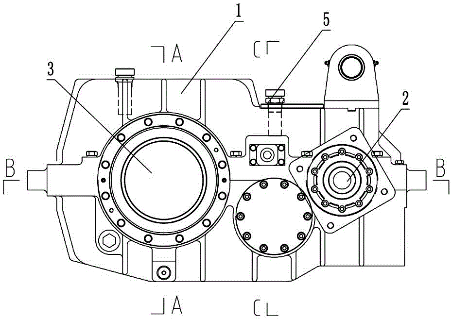
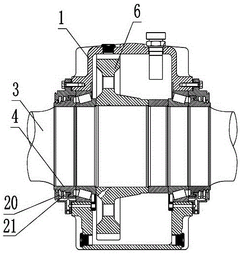
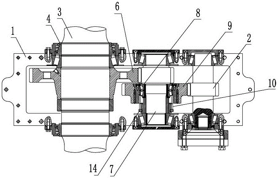
[0017] Such as Figure 1-5 As shown, the driving gearbox transmission device of the subway engineering vehicle of the present invention includes a gearbox body 1, and a power input gear shaft 2 and an axle 3 are arranged in the gearbox body 1 through a bearing body. The two ends of the axle 3 pass through The double-sealed combination and two oil-return channel labyrinth seal ring 4 extends out of the gear box body 1. A breathable cap 5 is arranged on the wall of the gear box body 1; the interference fit of the axle 3 is covered with a first transmission gear 6, a gear box A transmi...


PUM


Abstract

The invention discloses a transmission device of a subway engineering vehicle drive gear box. The transmission device comprises an input gear shaft and an axle which are arranged in the gear box and is characterized in that two ends of the axle extend out of the gear box in a sealed manner, and the wall of the gear box is provided with a breathable cap; a first transmission gear sleeves the axle in an interference fit manner, a transmission gear shaft located between the input gear shaft and the axle is arranged in the gear box, a second transmission gear sleeves the transmission gear shaft through a tapered-roller bearing and is provided with an outer gear and an inner gear, and the tapered-roller bearing is positioned onto the transmission gear shaft through a gear sleeve and a distance ring; a duplicate gear slidably sleeves the transmission gear shaft, and a gear shifting mechanism used for driving the duplicate gear is arranged in the gear box; the input gear shaft meshes with the outer gear of the second transmission gear, the duplicate gear meshes with the inner gear of the second transmission gear, and the first transmission gear meshes with the transmission gear shaft. By the transmission device, various working condition requirements of a subway engineering vehicle under complex working environments are satisfied, and automatic neutral returning and gear shifting are achieved.

Description

Technical field [0001] The invention relates to a subway engineering vehicle, in particular to a driving gear box transmission device of a subway engineering vehicle. Background technique [0002] The subway project consists of two parts: the power part and the grinding trolley. The operating speed is 3-10km / h. During the operation, the grinding motor on the grinding device is used to rough and finely grind the surface of the rail head to eliminate the wave-shaped wear of the rail. , Rail fat edge, saddle wear, weld depression and fish scale cracks and other defects, so as to improve the contour of the working part of the rail head and improve the reliability of rail transit safety. [0003] The existing subway line rails and locomotive line rails need to be polished and trimmed. Due to the difference in wheel gauge and curved track of the above two types of rails, power transmission can only be carried out by different driving devices at present. This greatly increases the design...

Claims


Application Information

Patent Timeline
IPC IPC(8): F16H3/32F16H3/04F16H61/30F16H57/029F16H61/22B61C9/00
CPCF16H3/04F16H3/32F16H57/029F16H61/22F16H61/30B61C9/00F16H2061/226
Inventor 田华军刘中令范乃则赵家栋张祥儒李耀苗圩巍
Owner ZHENGZHOU RES INST OF MECHANICAL ENG CO LTD
Why Eureka
Try Eureka