
A pump casing of a screw vacuum pump

A technology for screw vacuum pumps and pump casings, which is applied to parts of pumping devices for elastic fluids, rotary piston type/oscillating piston type pump parts, pump elements, etc., and can solve the problem of poor fluidity of anti-corrosion metals and anti-corrosion of cast iron Poor performance, one-time access to the pump casing and other problems, to achieve the effect of improving corrosion resistance, eliminating maintenance, and good cooling effect

Active Publication Date: 2019-02-12
ZHEJIANG CHUANGWEI VACUUM EQUIP CO LTD
View PDF9 Cites 0 Cited by
  • Summary
  • Abstract
  • Description
  • Claims
  • Application Information

AI Technical Summary

Problems solved by technology

At present, the pump casings of screw vacuum pumps on the market are all integrally formed. Due to the poor fluidity of anti-corrosion metals, it is impossible to obtain the pump casing at one time through casting and other processes; therefore, the pump casings of screw vacuum pumps on the market are all made of cast iron materials through casting. , the pump casing formed by casting has a cooling water cavity. The cast iron has good fluidity after melting, so it is suitable for the casting process, but the corrosion resistance of cast iron is poor, and the formed pump casing needs to be coated with anti-corrosion coating in the pump cavity Anti-corrosion treatment such as coating or fixed inner bushing can achieve anti-corrosion, but after a period of use, it is necessary to maintain the anti-corrosion coating or inner bushing to avoid wear and tear of the anti-corrosion coating or inner bushing. The pump casing is corroded, resulting in higher operating costs

Method used


Image

  • A pump casing of a screw vacuum pump
  • A pump casing of a screw vacuum pump
  • A pump casing of a screw vacuum pump

Examples


Embodiment Construction

[0025] The following are specific embodiments of the present invention and in conjunction with the accompanying drawings, the technical solutions of the present invention are further described, but the present invention is not limited to these embodiments.

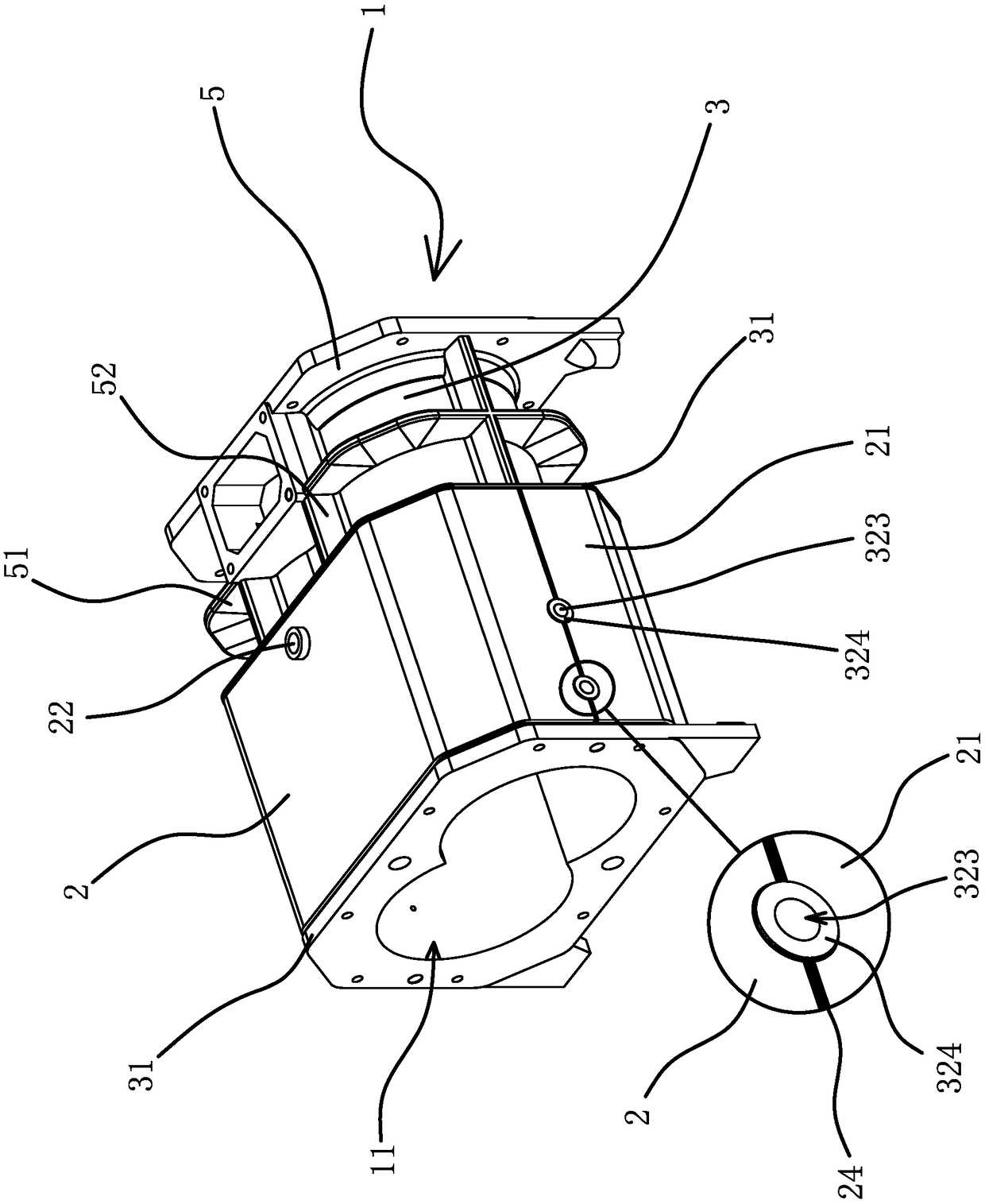
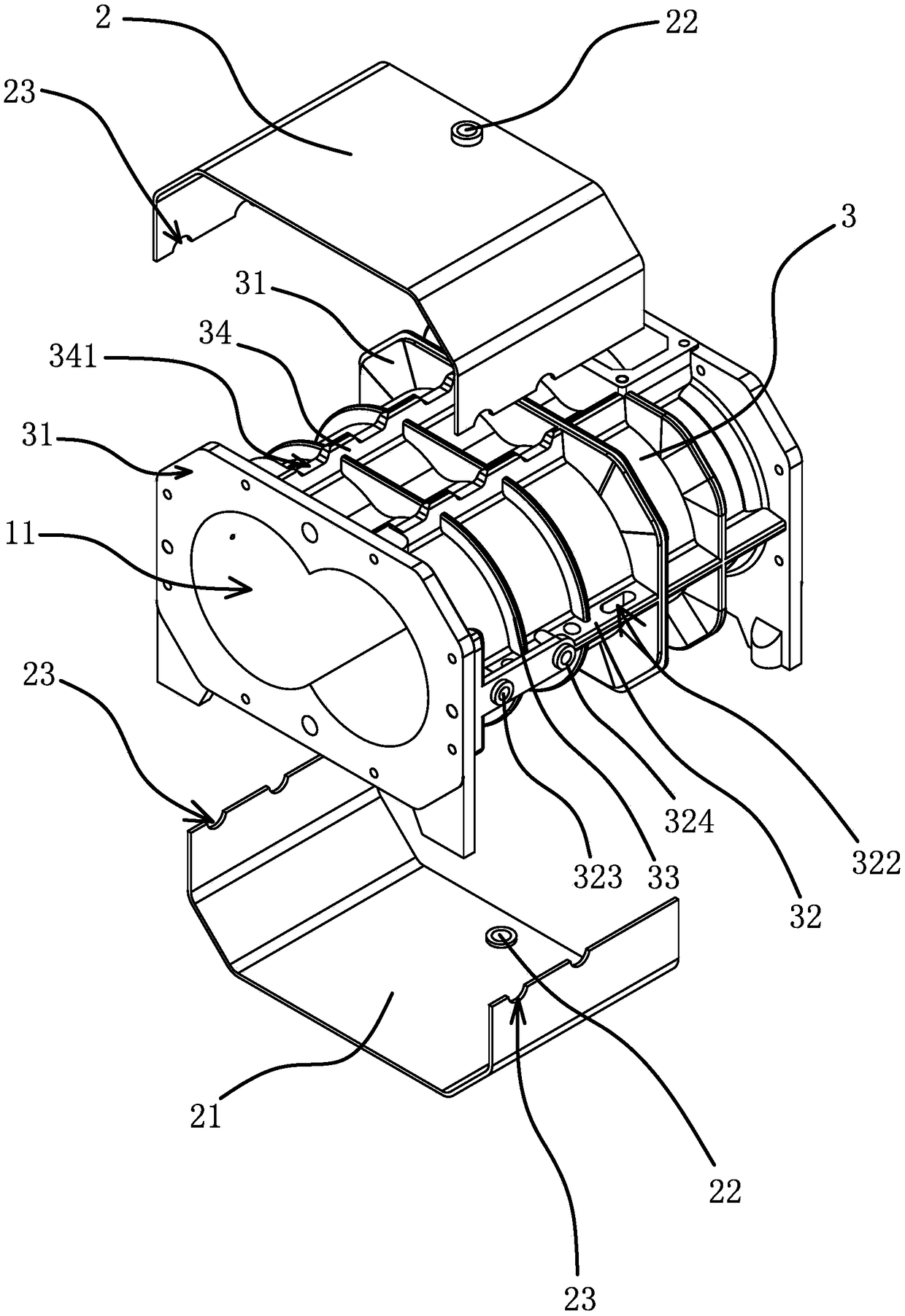
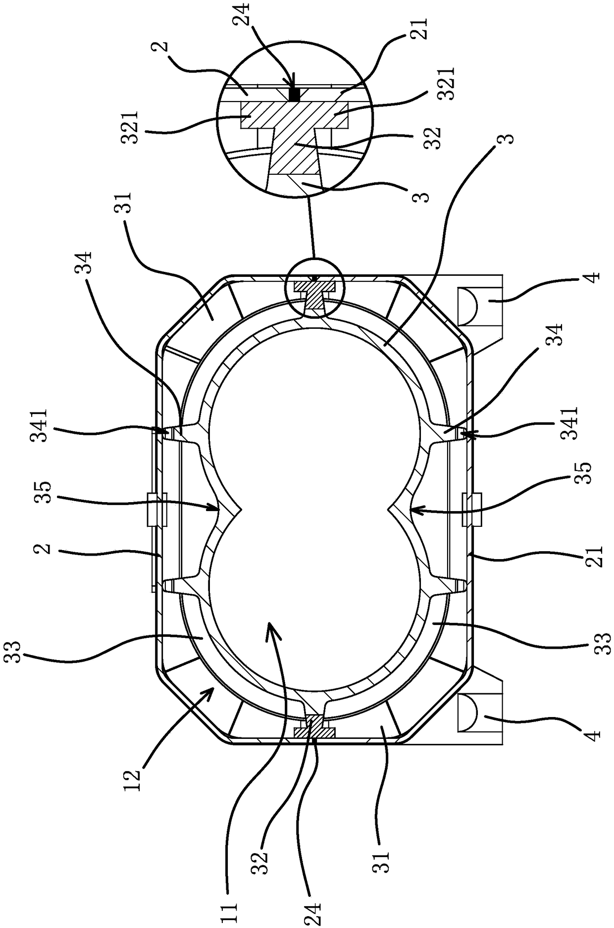
[0026] Such as Figure 1 to Figure 4 As shown, the pump casing of the screw vacuum pump includes a pump body 1 with a pump chamber 11, and a cooling water chamber 12 inside the pump body 1. The pump body 1 is composed of several outer casings 6 and an inner casing 3 made of anti-corrosion metal. In this embodiment, the outer casing 6 includes an outer casing one 2 and an outer casing two 21, and the inner casing 3 has the above-mentioned pump chamber 11. Specifically, the inner casing 3 can be made of stainless steel or titanium alloy or Monel alloy or Hastelloy. Alloy precision casting.

[0027] Such as Figure 2 to Figure 5 As mentioned above, the inner housing 3 has two annular fixing ribs 31 along the length directio...


PUM


Abstract

The invention provides a pump case of a screw vacuum pump, belongs to the technical field of screw vacuum pumps, and aims to solve the technical problem that a conventional pump case of the screw vacuum pump is high in use cost. The pump case of the screw vacuum pump comprises a pump body with a pump chamber, wherein a cooling water cavity is formed in the pump body; the pump body consists of a plurality of outer housings and an inner housing made of corrosion-resistant metal; the pump chamber is formed in the inner housing; two ring-shaped fixing flanges are formed on the outer wall of the inner housing in the length direction; the outer housings are arranged between the two fixing flanges and are in ring-shaped distribution; the two end edges of the outer housings and the fixing flanges are welded and sealed together; opposite edges of the adjacent outer housings are welded and sealed; and the cooling water cavity is formed between the outer housings and the inner housing. The pump case has the advantage that the corrosion resistance of the pump case can be realized without arranging a corrosion-resistant structure on the pump case under the condition of guaranteeing cooling of the pump case.

Description

technical field [0001] The invention belongs to the technical field of screw vacuum pumps, and relates to a pump shell of a screw vacuum pump. Background technique [0002] The screw vacuum pump is an air extraction device that uses two screws to rotate synchronously and at high speed in the pump body to generate air suction and exhaust. It is widely used in major domestic pharmaceutical and chemical companies in dusty gas occasions. [0003] When the screw vacuum pump is in use, it will generate heat due to the extrusion of the gas, so a cooling water cavity needs to be installed in the pump casing. At the same time, the gas pumped by the screw vacuum pump is corrosive during use, so the inner wall of the pump cavity of the pump casing needs to be treated with anti-corrosion treatment. At present, the pump casings of screw vacuum pumps on the market are all integrally formed. Due to the poor fluidity of anti-corrosion metals, it is impossible to obtain the pump casing at o...

Claims


Application Information

Patent Timeline
Patent Type & Authority Patents(China)
IPC IPC(8): F04C29/00F04C29/04
CPCF04C29/00F04C29/042F04C2240/30
Inventor 柯建汝
Owner ZHEJIANG CHUANGWEI VACUUM EQUIP CO LTD
Learn More