
Rotary compressors and refrigeration cycle units

A rotary compressor and compression mechanism technology, applied in the field of rotary compressors and refrigeration cycle devices, can solve the problems of increased compression loss, increased noise, and inability to fully improve compression performance, so as to improve reliability and sound insulation The effect of performance improvement

Active Publication Date: 2018-11-23
TOSHIBA CARRIER CORP
View PDF5 Cites 0 Cited by
  • Summary
  • Abstract
  • Description
  • Claims
  • Application Information

AI Technical Summary

Problems solved by technology

[0009] However, if the compressed working fluid is simultaneously discharged from a plurality of discharge ports of the same diameter, the discharge pressure pulsation will resonate and the noise will increase, and the compression loss due to the opening and closing timing of the discharge valve will increase and performance will tend to decrease.
Therefore, the compression performance cannot be sufficiently improved by providing only two discharge ports, and there is a reality that it is difficult to put it into practice.
In addition, in the rotary compressor described in Patent Document 1, the diameter of the discharge port provided in the bearing is larger than the diameter of the discharge port provided in the separator, the flow path of the working fluid is branched, and more working fluid is used. The structure that flows in the bearing, but the sound insulation performance of the bearing part is lower than that of the partition, and if more refrigerant is discharged from this part, there is a problem that the noise will increase

Method used


Image

  • Rotary compressors and refrigeration cycle units
  • Rotary compressors and refrigeration cycle units
  • Rotary compressors and refrigeration cycle units

Examples


no. 1 Embodiment approach

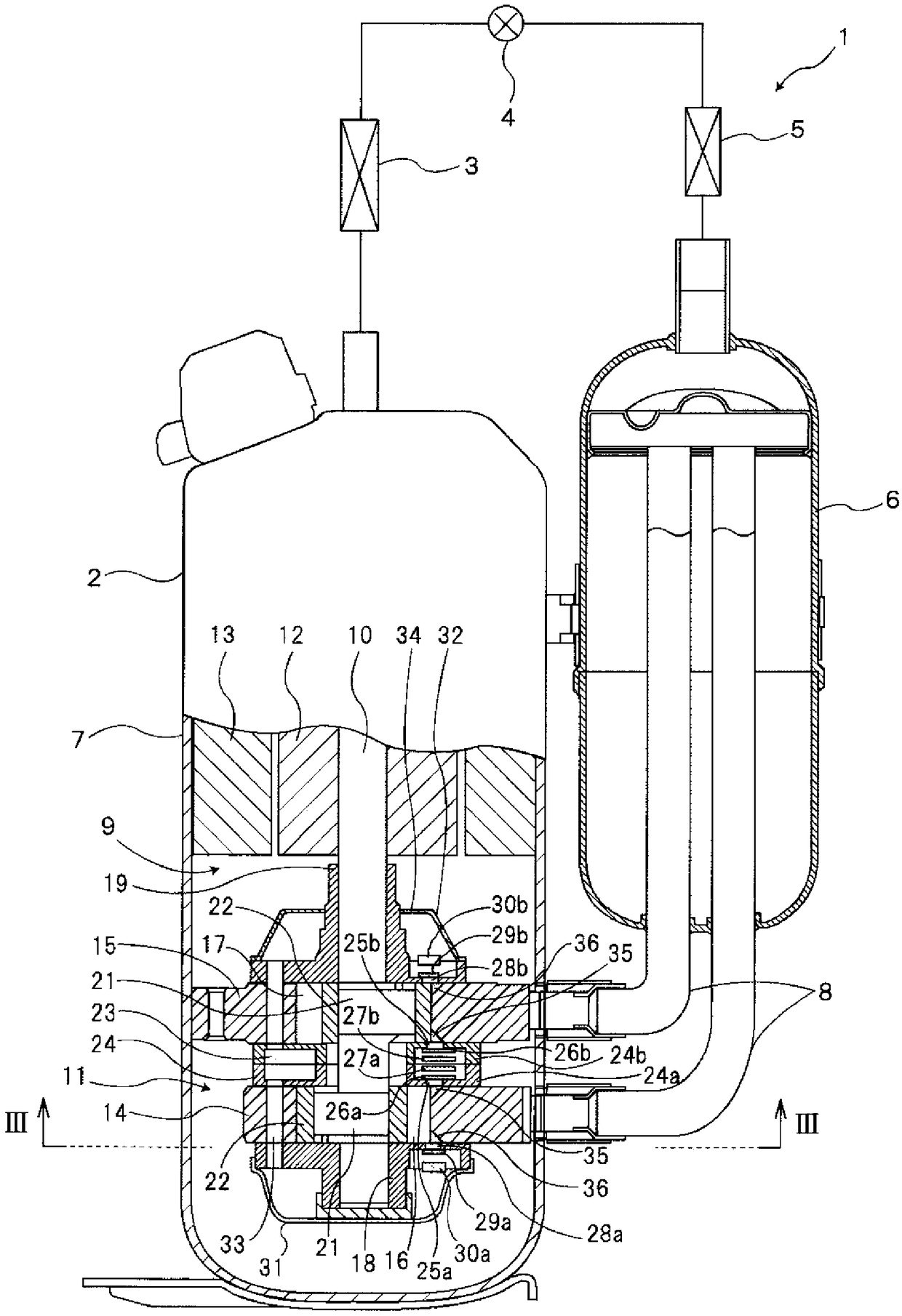
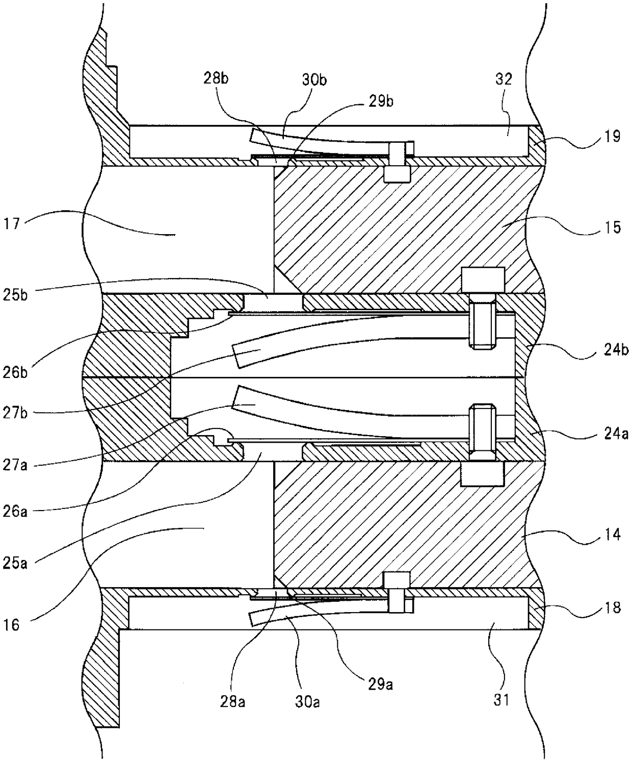
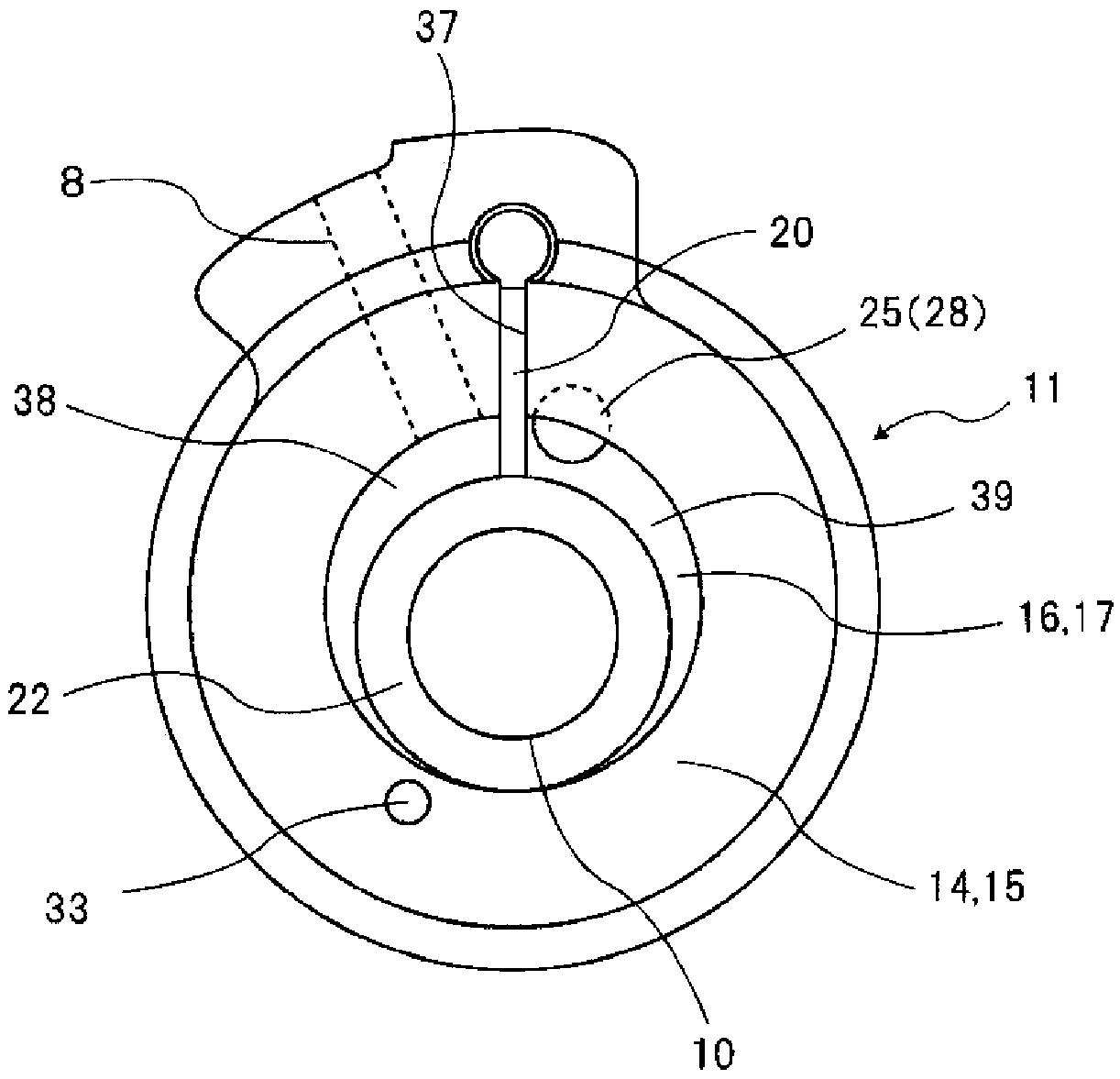
[0025] refer to Figure 1 to Figure 3 The rotary compressor of the first embodiment and the refrigeration cycle apparatus including the same will be described.

[0026] figure 1 The overall structure of the refrigeration cycle device is shown. The refrigeration cycle device 1 is provided with a compressor main body 2 connected to the compressor main body 2, and condenses gas refrigerant as a high-pressure and high-temperature working fluid discharged from the compressor main body 2 to convert it into a A condenser 3 for forming liquid refrigerant, an expansion device 4 connected to the condenser 3 to decompress the liquid refrigerant, an evaporator 5 for evaporating the liquid refrigerant expanded in the expansion device 4, and separating the refrigerant into gas phase and Accumulator 6 in liquid phase. The accumulator 6 and the compressor main body 2 are connected by the suction flow path 8 through which the working fluid flows, and constitute a rotary compressor.

[0027]...

no. 2 Embodiment approach

[0065] In the first embodiment, the case where the blades and the rollers of the compression mechanism are separate components has been described, but according to the present invention, as the second embodiment, an oscillating type (Japanese : Singtaip).

no. 3 Embodiment approach

[0067] In addition, the number of cylinders of the rotary compressor is two in the above example, but the same effect can be obtained also in a type having three or more cylinders as the third embodiment.

[0068] In addition, the present invention is an invention to provide a refrigeration cycle apparatus including the rotary compressor in each of the above-described embodiments, such as, for example, figure 1 As shown, it is composed of the following parts: the compressor main body 2 having the above-mentioned structure is connected to the compressor main body 2, and the high-pressure and high-temperature working fluid that is discharged from the compressor main body 2, that is, the gas refrigerant is condensed and turned into a liquid. A condenser 3 for the refrigerant, an expansion device 4 that decompresses the liquid refrigerant connected to the condenser 3, an evaporator 5 that evaporates the liquid refrigerant expanded by the expansion device 4, and an energy storage de...


PUM


Abstract

The present invention is a rotating compressor provided with a compression mechanism part constituted of: an airtight case; a plurality of cylinders that are partitioned by partitioning plates inside the airtight case and that have intake ports and cylinder chambers; and rollers that are disposed inside the cylinder chambers and to which eccentric rotation is given, wherein a compression chamber is formed in each of the cylinder chambers. In the compression mechanism part, outlet ports from which working fluid that has been compressed in the compression chambers is discharged are individually provided in the partitioning plates and in bearings that close the cylinders, and the outlet ports provided in the partitioning plates are formed so that the opening areas thereof are greater than the opening areas of the outlet ports provided in the bearings.

Description

technical field [0001] The present invention relates to a rotary compressor for compressing a working fluid such as a gas refrigerant, and a refrigeration cycle apparatus including the same. Background technique [0002] Conventionally, a rotary compressor that compresses a working fluid such as a gas refrigerant forms a cylinder chamber in the cylinder by closing both ends of the cylinder with a closing member, and uses an eccentrically rotating roller and a reciprocating blade to form a cylinder chamber inside the cylinder. Divided into a suction chamber and a compression chamber, the working fluid sucked into the suction chamber is compressed in the compression chamber, and the compressed working fluid is discharged from a discharge port formed in the blocking member. In such a rotary compressor, in recent years, there has been a need to increase the amount of working fluid to be compressed once, increase the capacity, and improve performance. In order to meet this requi...

Claims


Application Information

Patent Timeline
Patent Type & Authority Patents(China)
IPC IPC(8): F04C18/356F04C23/00F04C29/06F04C29/12
CPCF04C18/356F04C23/00F04C29/06F04C29/12
Inventor 志田胜吾
Owner TOSHIBA CARRIER CORP
Learn More