
Novel smelting furnace structure

A smelting furnace, a new type of technology, applied in the field of new smelting furnace structure, can solve the problems of small smelting equipment, structural form, poor heating efficiency, unfavorable safety production, etc., and achieve good melting effect, low cost, and occupying an area The effect of area reduction

Inactive Publication Date: 2017-05-17
杨配媛
View PDF0 Cites 0 Cited by
  • Summary
  • Abstract
  • Description
  • Claims
  • Application Information

AI Technical Summary

Problems solved by technology

At present, the structure of the small smelting furnace is simple, the structural form and the heating efficiency are extremely poor, waste energy, the energy utilization rate is low, and there are large safety hazards, which is not conducive to safe production
People try to study a small and efficient smelting furnace, but so far, the technical problems of this energy-saving and efficient small smelting equipment have not been effectively solved

Method used


Image

  • Novel smelting furnace structure

Examples


Embodiment Construction

[0020] The following will be further described in conjunction with the accompanying drawings, not to limit the scope of the present invention.

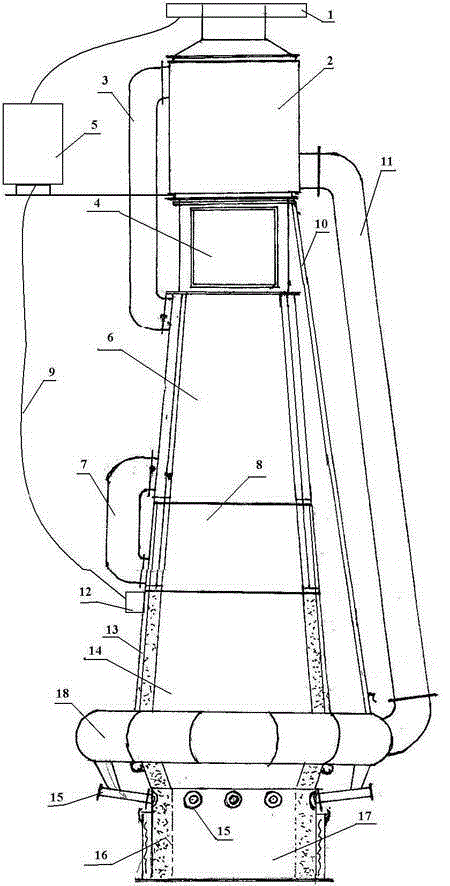
[0021] Referring to the accompanying drawings, the present invention includes a combustion chamber 17, a melting chamber 14, a small wind bladder 8 and a large wind bladder 6. The combustion chamber 17 is located at the bottom, and its inner wall is provided with a refractory layer 16. The sides of the combustion chamber 17 There is a slag outlet. The melting chamber 14 is located on the upper part of the combustion chamber 17 and has a cylindrical structure. The outer wall of the cylindrical structure is wrapped by a cooling layer 13, and its inner wall is filled with a refractory layer 16. Between the combustion chamber 17 and the melting chamber 14, a The wind control device 18 is provided with a regulating valve 15 outside the wind control device 18, and the regulating valve 15 is used to adjust the magnitude of the wind force and...


PUM


Abstract

The invention relates to a novel smelting furnace structure which comprises a combustion chamber, a smelting chamber, a small air container and a large air container. The combustion chamber is located at the bottommost part, and a fire-resisting layer is arranged on the inner wall of the combustion chamber. The smelting chamber is located at the upper portion of the combustion chamber and is of a cylindrical structure. The outer wall of the cylindrical structure is wrapped by a cooling layer, and the inner wall of the cylindrical structure is filled with a fire-resisting layer. An air control device is arranged between the combustion chamber and the smelting chamber. The small air container is located at the upper portion of the smelting chamber, and the large air container is located above the small air container. A small air pipeline is arranged at the outer portion of the small air container. One end of the small air pipeline communicates with the small air container, and the other end of the small air pipeline communicates with the large air container. According to the novel smelting furnace structure, the heat efficiency of the equipment is high through the hot air pipeline, sufficient utilization on heat energy is enhanced through an unique and complex hot air flowing structure in a furnace, the heat transfer speed is high, and the heating efficiency is high.

Description

technical field [0001] The invention belongs to the technical field of smelting equipment manufacturing, and in particular relates to a novel smelting furnace structure. Background technique [0002] With the increasingly tense relationship between international energy supply and demand, the energy consumption of smelting furnaces has attracted people's attention. At present, the society urgently needs to develop safe and energy-saving smelting equipment. At present, the small smelting furnace has a simple structure, poor structural form and heating efficiency, waste of energy, low energy utilization rate, and relatively large safety hazards, which are not conducive to safe production. People try to study a kind of small-scale high-efficiency smelting furnace, but up to now, also do not effectively solve the technical problem of this energy-saving and high-efficiency small-scale smelting equipment. Contents of the invention [0003] The present invention overcomes the def...

Claims


Application Information

Patent Timeline
Patent Type & Authority Applications(China)
IPC IPC(8): F27B14/00F27B14/08
Inventor 杨配媛
Owner 杨配媛
Learn More