Assembled steel-concrete combination structure bridge and construction method
A combined structure and concrete technology, which is applied in the direction of erecting/assembling bridges, bridges, bridge parts, etc., can solve the problems that the combined force effect is not as good as the uniform arrangement of shear nails, the difficulty of installing prefabricated slabs, and the increase in the amount of concrete cast in place, etc. Achieve the effect of reasonable force, improve construction quality, and fast and simple construction
- Summary
- Abstract
- Description
- Claims
- Application Information
AI Technical Summary
Problems solved by technology
Method used
Image
Examples
Embodiment 2
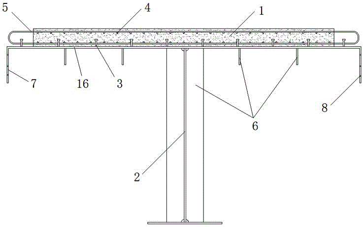
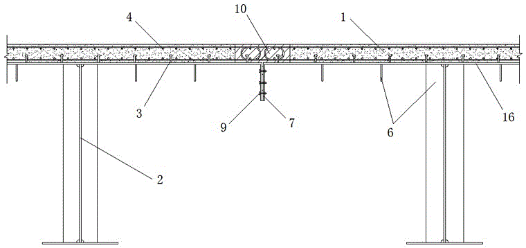
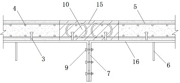
[0047] Embodiment two: if Figure 4~6 As shown, in this embodiment, a gap of 100 to 300 mm is left between the two connected longitudinal ribs 7, the longitudinal ribs are L-shaped, and bolt holes are provided on the web 11 of the L-shaped longitudinal ribs. The longitudinal ribs between two adjacent composite beams are connected together by connecting steel plates 12 and bolts 9, and the connecting steel plates 12 and webs 11 are connected by bolts 9; The reinforcement cage 13 between the two longitudinal ribs is also poured with joint concrete 10 in the gap between the two longitudinal ribs, and the longitudinal rib 7 is welded with the shear connector 3 that connects the joint concrete and the upper flange steel plate together. When the bridge deck is wide, the gaps between the longitudinal ribs form small longitudinal girders, which is conducive to the stress of the main girder and reduces the construction amount of concrete wet joints.
[0048] The construction method of...
Embodiment 3
[0049] Embodiment three: as Figure 7 As shown, the difference between this embodiment and Embodiment 1 is that the structure of the longitudinal ribs is different, and the lower side of the longitudinal ribs also has a web 11 bent inward at 90° so that the longitudinal ribs form an L-shaped structure.
Embodiment 4
[0050] Embodiment four: as Figure 8 As shown, the difference between the present embodiment and the second embodiment is that the steel girder section of the present embodiment is a box-shaped section.
PUM
 Abstract
Description
Claims
Application Information
 - R&D
- Intellectual Property
- Life Sciences
- Materials
- Tech Scout
- Unparalleled Data Quality
- Higher Quality Content
- 60% Fewer Hallucinations
Browse by: Latest US Patents, China's latest patents, Technical Efficacy Thesaurus, Application Domain, Technology Topic, Popular Technical Reports.
© 2025 PatSnap. All rights reserved.Legal|Privacy policy|Modern Slavery Act Transparency Statement|Sitemap|About US| Contact US: help@patsnap.com


