
Cage type CT scanner

A scanner and cage-type technology, applied in computerized tomography scanners, instruments for radiological diagnosis, medical science, etc., can solve problems such as heavy load, very high requirements on the ground of the work site, and reduced mechanical efficiency of the engine. Achieve the effect of reducing the weight and volume of the whole machine, reducing the operating burden and reducing the design size

Active Publication Date: 2017-05-17
SUZHOU INST OF BIOMEDICAL ENG & TECH CHINESE ACADEMY OF SCI
View PDF5 Cites 9 Cited by
  • Summary
  • Abstract
  • Description
  • Claims
  • Application Information

AI Technical Summary

Problems solved by technology

Patent No. 201510627371 is an example. It mainly improves the whole machine by reducing the volume and weight of the CT scanner, reducing the rotation arc of the rotating parts and the vibration amplitude of the whole machine. The design part of the drag chain in this patent is The initiative of the research team, but at the same time it also brought about the problem of dynamic balance. It is necessary to eliminate the eccentric force of the transmission through balance correction and other measures to reduce and eliminate the vibration of the CT scanner itself to reduce the requirements for the working ground.
[0005] The bedside CT scanner has the characteristics of light weight, small size, and flexible movement. However, the current bedside CT scanners on the market all adopt a ring-shaped structure, that is, the rotating part is a large ring, and the engine is fixed on the frame. The transmission and connection of the components drives the big ring to rotate. Usually, the X-ray source and detector are fixedly installed on the turntable, and the heavy load often reduces the mechanical efficiency of the engine. The power supply demand for the field shelter is relatively high. In the United States Take the small CT scanner designed by Neurologica Company as an example, which adopts the belt-covering method to realize synchronous driving. The main advantage of this method is that the center of gravity is stable. The disadvantage is that the ground requirements of the work site are very high, and it cannot be scanned in general ground and field environments. Moreover, due to the inherent factors of pulley transmission, such as belt slippage, locking, etc., it cannot be satisfied with high-precision field rescue systems.

Method used


Image

  • Cage type CT scanner
  • Cage type CT scanner
  • Cage type CT scanner

Examples


Embodiment Construction

[0029]The present invention will be further described in detail below in conjunction with the accompanying drawings, so that those skilled in the art can implement it with reference to the description.

[0030] It should be understood that terms such as "having", "comprising" and "including" as used herein do not entail the presence or addition of one or more other elements or combinations thereof.

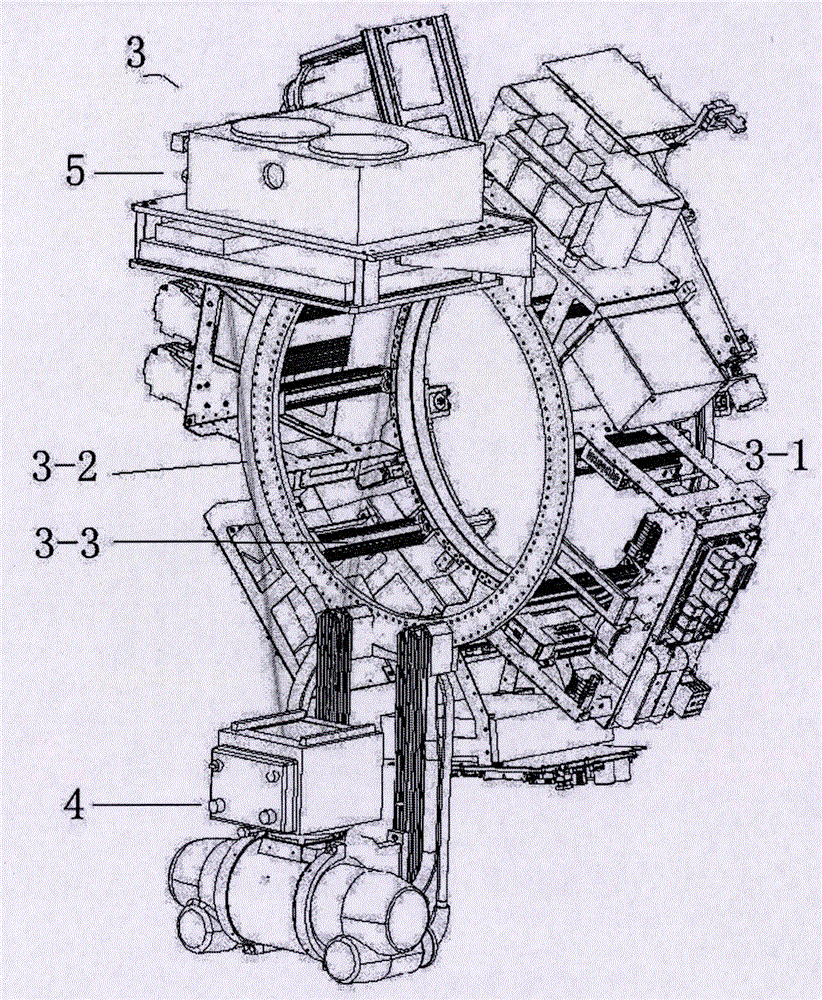
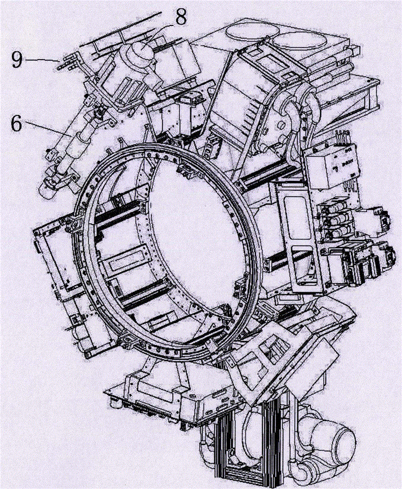
[0031] like figure 1 and figure 2 As shown, the present invention provides a medical cage CT scanner, comprising:

[0032] Frame 1, which is erected vertically on the moving device 2 of the CT scanner; a cage-shaped rotating part 3, comprising a first rotating fitting 3-1, a second rotating fitting 3-2 and connecting the first rotating fitting 3-1 and the edge 3-3 of the second rotating fitting 3-2, the first rotating fitting 3-1 is rotated on the frame 1 through a slewing bearing, and the cage-shaped rotating part 3 and the frame 1 are circular Ring structure, the center of t...


PUM


Abstract

The invention discloses a cage type CT scanner, which reduces and eliminates vibration of the CT scanner itself mainly by reducing the volume and weight of the CT scanner, the rotational radian of a rotating part and the vibration amplitude of the whole machine at the same time in order not to balance correction to eliminate the drive eccentric force and other measures. The cage type CT scanner eliminates a mechanical transmission chain belt cover to reduce the number of components in a motor structure, which not only reduces the cost, also meets the work requirements of the ground, and thus the CT scanner using site becomes wider.

Description

technical field [0001] The present invention relates to a medical device, more specifically, the present invention relates to a cage CT scanner. Background technique [0002] Cone beam CT has developed rapidly since its clinical application at the beginning of this century. In future high-tech wars, field agitation medical equipment will be an important medical institution for the treatment of wounded in wartime and an important medical component of major disaster relief. However, the field environment is harsh, and the traditional large CT scanner not only takes up a lot of space, but also cannot provide timely bedside scanning services for critically ill patients. [0003] At present, there are several miniaturized CT products, but all of them adopt technologies similar to traditional CT, such as scintillator detector array, slip ring data transmission and spiral scanning, and can only perform tomographic reconstruction. The X-ray source and detector are fixedly installed...

Claims


Application Information

Patent Timeline
IPC IPC(8): A61B6/03
CPCA61B6/032A61B6/035A61B6/4064A61B6/4208A61B6/44A61B6/4405A61B6/4435A61B6/4085A61B6/4429
Inventor 高欣梁志远
Owner SUZHOU INST OF BIOMEDICAL ENG & TECH CHINESE ACADEMY OF SCI
Learn More