
Wide-band radio frequency power amplifier with standby mode, chip and communication terminal

A radio frequency power and amplifier technology, which is applied in the field of radio frequency integrated circuits, can solve the problems of limiting the bandwidth of amplifiers and wasting power consumption, and achieve the effects of reducing power consumption, reducing equivalent capacitance, and improving bandwidth

Inactive Publication Date: 2017-05-10
VANCHIP TIANJIN TECH
View PDF4 Cites 0 Cited by
  • Summary
  • Abstract
  • Description
  • Claims
  • Application Information

AI Technical Summary

Problems solved by technology

Its bandwidth is usually limited by the equivalent capacitance and resistance at the input, where a large part of the input capacitance comes from the parasitic capacitance (CGD) between the input (gate) and output (drain) of the single-transistor amplifier, due to the The existence of the Le effect, the equivalent capacitance of this part of the parasitic capacitance at the input limits the bandwidth of this amplifier
[0004] On the other hand, in a high-power RF power amplifier, a large quiescent current is usually required, such as 100mA. For a 5V-powered RF circuit, the power consumption of the RF power amplifier itself will reach 500mW, which is very considerable. power consumption
In many cases, we do not always need the RF power amplifier to amplify the input signal, so when the RF power amplifier is not required to work, the quiescent current of the RF power amplifier itself causes a serious waste of power consumption

Method used


Image

  • Wide-band radio frequency power amplifier with standby mode, chip and communication terminal
  • Wide-band radio frequency power amplifier with standby mode, chip and communication terminal
  • Wide-band radio frequency power amplifier with standby mode, chip and communication terminal

Examples


Embodiment Construction

[0029] The technical content of the present invention will be further described in detail below in conjunction with the accompanying drawings and specific embodiments.

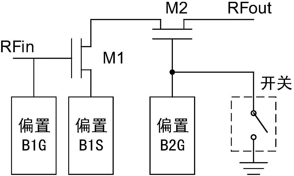
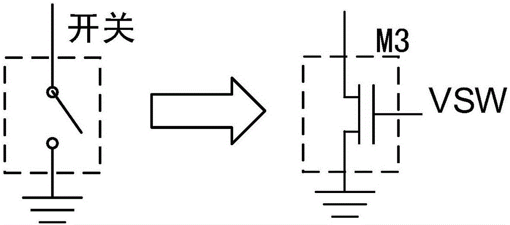
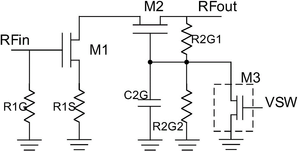
[0030] The basic technical idea of ​​the present invention is that in the radio frequency power amplifier, a cascode structure is formed by using a depletion-type common-source transistor and an enhancement-type common-gate transistor, and a switch is introduced into the gate of the common-gate transistor, thereby effectively controlling the wideband radio frequency The power amplifier works in amplification mode or standby mode. In this way, the broadband radio frequency power amplifier can consume a very small quiescent current when it does not need to work, so as to achieve the purpose of saving energy and reducing consumption.

[0031] figure 1 An embodiment of a broadband RF power amplifier with a standby mode provided by the present invention is shown. In this embodiment, the broadband radio frequency ...


PUM


Abstract

The invention discloses a wide-band radio frequency power amplifier with a standby mode, a chip and a communication terminal. The wide-band radio frequency power amplifier comprises a depletion type transistor, an enhancement transistor and a switch; the depletion type transistor is connected according to a common source mode, a grid is used as input end of the wide-band radio frequency power amplifier, and a drain is used as the source of the enhancement transistor; the enhancement transistor is connected according to a common grid mode, and the drain is used as an output end of the wide-band radio frequency power amplifier; and one end of the switch is connected with the grid of the enhancement transistor, and the other end is grounded. According to the wide-band radio frequency power amplifier provided by the invention, by means of the novel and smart common source and common grid structure, the equivalent capacitance of the input end caused by the Miller effect is effectively reduced, thereby effectively improving the pole frequency and the bandwidth of the wide-band radio frequency power amplifier. Due to the implementation of the standby mode, the power consumption level of the wide-band radio frequency power amplifier is greatly reduced.

Description

technical field [0001] The invention relates to a radio frequency power amplifier, in particular to a broadband radio frequency power amplifier with a standby mode, and also to a chip and a communication terminal including the broadband radio frequency power amplifier, belonging to the technical field of radio frequency integrated circuits. Background technique [0002] Broadband RF power amplifiers refer to RF power amplifiers that do not require tuning over a wide frequency range. It generally uses broadband components such as transmission lines and transformers as the interstage network and output network of the amplifier. Its work efficiency is lower than that of tuned RF amplifiers, but it is convenient to improve reliability and simplify maintenance and implementation in the case of rapidly changing frequency for communication. auto-adjust. [0003] In existing broadband radio frequency power amplifiers, single-transistor amplifiers connected in the form of a common s...

Claims


Application Information

Patent Timeline
Patent Type & Authority Applications(China)
IPC IPC(8): H03F3/217H03F3/213H03F1/42H03F1/02
CPCH03F1/0205H03F1/42H03F3/213H03F3/217
Inventor 白云芳林升
Owner VANCHIP TIANJIN TECH
Learn More