Intelligent automobile data recorder system
A technology of driving recorder and circuit, which is applied in the direction of registration/indication of vehicle operation, instrumentation, registration/indication, etc., which can solve problems such as the reduction of accident rate, achieve beautification of the vehicle body, ensure safety and stable and reliable operation, and stable and reliable operation Effect
- Summary
- Abstract
- Description
- Claims
- Application Information
AI Technical Summary
Problems solved by technology
Method used
Image
Examples
Embodiment 1
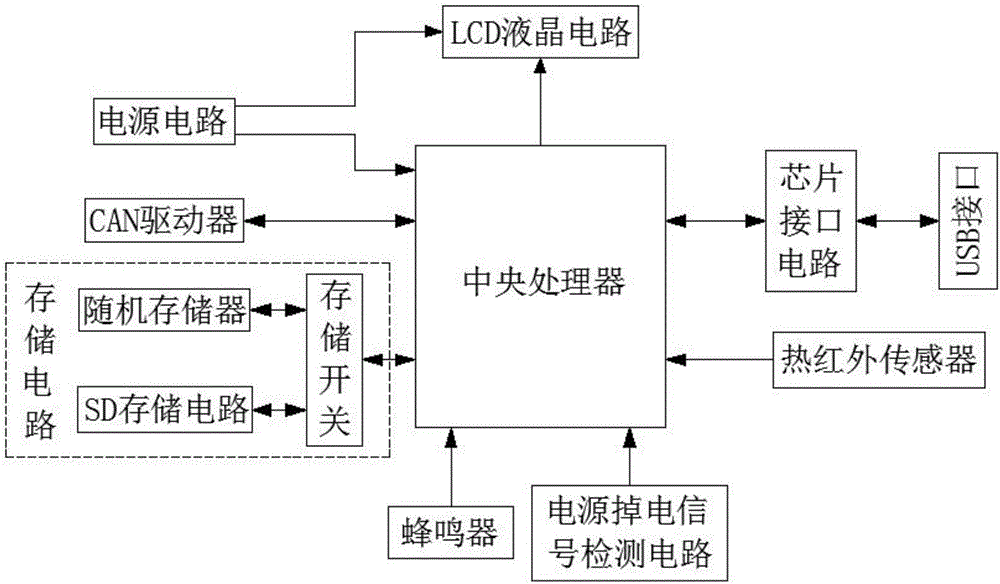
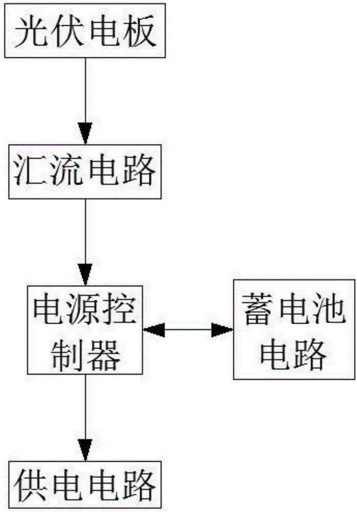
[0045] An intelligent driving recorder system, which uses solar power to form the main power circuit of the power circuit, can effectively use the solar energy in clean energy, convert the solar energy into electrical energy, and supply power for it, so that it can effectively save non-renewable resources. , and the installed photovoltaic panels can further play the role of beautifying the car body, achieving practical, safe, and beautifying effects. Its stable power supply effect effectively guarantees the safety, stability and reliability of the driving recorder. When running, it can record any events around the car that can be visually photographed by the driving recorder during the driving process in real time or when it is temporarily stopped, providing a strong guarantee for later data calls, such as figure 1 , figure 2 , image 3 As shown, the following setting structure is specially adopted: a power supply circuit, a central processing unit, a storage circuit, a CAN ...
Embodiment 2
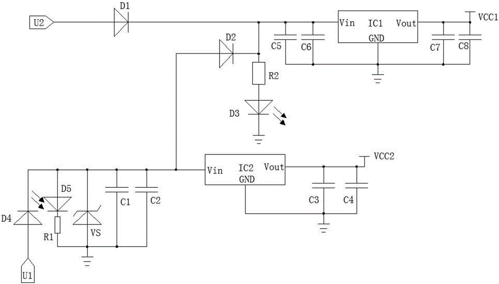
[0047] This embodiment is further optimized on the basis of the above-mentioned embodiment, such as figure 1 , figure 2 , image 3 As shown in the figure, in order to better realize the present invention, the following setting structure is specially adopted: a liquid crystal display circuit is also arranged in the driving recorder system, the central processing unit is connected to the liquid crystal display circuit, and the liquid crystal display circuit is connected to the power supply. The power supply circuit is also provided with a liquid crystal power supply circuit. The liquid crystal power supply circuit includes a power supply chip IC2, a capacitor C3 and a capacitor C4. The output end of the input voltage regulator circuit is connected to the Vin pin of the power supply chip IC2. The capacitor C3 is connected in parallel with the capacitor C4 and is connected between the Vout pin and the GND pin of the power chip IC2.
Embodiment 3
[0049] This embodiment is further optimized on the basis of any of the above embodiments, such as figure 1 , figure 2 , image 3 As shown in the figure, in order to better realize the present invention, the following setting structure is specially adopted: a diode D5, a resistor R1, a voltage regulator tube VS, a capacitor C1, a capacitor C2, and a diode D5 are arranged in the input voltage regulator circuit. The positive pole is connected to the negative pole of the diode D4, the negative pole of the Zener tube VS, and the positive pole of the diode D2 respectively. The negative pole of the diode D5 is connected to the ground through the resistor R1, the positive pole of the Zener tube VS is grounded, and the capacitor C1 and the capacitor C2 are connected in parallel with the Zener tube VS. Both ends of , and are set at the output side of the Zener tube VS.
PUM
 Abstract
Description
Claims
Application Information
 - R&D
- Intellectual Property
- Life Sciences
- Materials
- Tech Scout
- Unparalleled Data Quality
- Higher Quality Content
- 60% Fewer Hallucinations
Browse by: Latest US Patents, China's latest patents, Technical Efficacy Thesaurus, Application Domain, Technology Topic, Popular Technical Reports.
© 2025 PatSnap. All rights reserved.Legal|Privacy policy|Modern Slavery Act Transparency Statement|Sitemap|About US| Contact US: help@patsnap.com


