


Quick Research
Generate reliable direction feasibility study reports for your R&D in just a few steps.

Technical Q&A
Discover and master advanced knowledge NOW. Basics, ideas, possibilities, all at once.

Find Solutions
As an expert in R&D theories, this can generate solutions to your technical problems instantly.

Evaluate Feasibility
Analyze your overall solution with one click, know your potential R&D risks in advance.

Monitor Landscape
Get weekly tech updates, stay abreast of the latest tech innovations and key insights.
Method and device for removing artifacts in images
A technology of image projection and projection, which is applied in the field of image processing, can solve problems such as poor motion artifact removal effect, failure to meet clinical needs, missed diagnosis or misdiagnosis, etc., to achieve good artifacts, remove artifacts, and avoid missed diagnosis and misdiagnosis Effect
- Summary
- Abstract
- Description
- Claims
- Application Information
AI Technical Summary
Problems solved by technology
Method used
Image

Examples
Embodiment 1
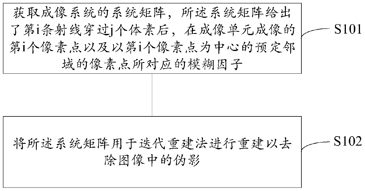
[0056] Step S101 is executed to obtain the system matrix of the CBCT system. In this embodiment, the actual test is performed on the phantom to obtain the spread function of the voxels in the phantom. Then, the system matrix is obtained based on the diffusion function of the voxels in the phantom. The phantom is provided with a plurality of markers, and the phantom may be provided with a plurality of markers at different positions in a matrix of uniform material. The absorption coefficient of the markers is different from that of the substrate, so It is easier to distinguish the marker and the matrix in the collected projection image. The phantom may be a cylinder, a hexahedron, or the like. The material of the matrix in the phantom can be low atomic number materials such as PMMA, and the marker can be high atomic number materials such as tungsten, aluminum, and iron.
[0057] The size of the projection image of the marker in at least one dimension is smaller than the pixel s...
Embodiment 2
[0086] The difference between this embodiment and the first embodiment is that the method of obtaining the system matrix in this embodiment is different from that in the first embodiment. In the first embodiment, the system matrix of the system is obtained by actual measurement of the phantom, while in this embodiment, the system matrix of the system is obtained by analysis. In this embodiment, the CBCT system is still taken as an example for description. Generally speaking, in the CBCT system, half of the angle rotated during the exposure integration time of the imaging system is defined as the projection angle. In this embodiment, in order to obtain a system matrix that can include motion blur, the angle rotated during the exposure integration time of the imaging system Subdivide, that is, divide it by a preset angle, the preset angle is smaller than the projection angle, after subdividing the angle rotated by the CBCT imaging system during the exposure integration time, the ...
PUM
 Abstract
Description
Claims
Application Information
 - R&D Engineer
- R&D Manager
- IP Professional
- Industry Leading Data Capabilities
- Powerful AI technology
- Patent DNA Extraction
Browse by: Latest US Patents, China's latest patents, Technical Efficacy Thesaurus, Application Domain, Technology Topic, Popular Technical Reports.
© 2024 PatSnap. All rights reserved.Legal|Privacy policy|Modern Slavery Act Transparency Statement|Sitemap|About US| Contact US: help@patsnap.com