
Low power consumption GPU (Graphic Process Unit) staining task and uniform staining array task field mapping structure

A low-power, high-task technology, applied in the direction of processor architecture/configuration, multi-program device, program control design, etc., can solve the problems of poor portability, GPU function, performance cannot be fully utilized, and constraints on display system development and independent development, etc. problems, to achieve the effect of low-power resource management methods

Active Publication Date: 2017-05-10
XIAN AVIATION COMPUTING TECH RES INST OF AVIATION IND CORP OF CHINA
View PDF3 Cites 8 Cited by
  • Summary
  • Abstract
  • Description
  • Claims
  • Application Information

AI Technical Summary

Problems solved by technology

Especially in the field of military use, foreign imported commercial GPU chips have hidden dangers in safety, reliability, security, etc., and cannot meet the needs of the military environment; "Blocking" and product "monopoly" make it difficult to obtain the underlying technical information of the GPU chip, such as register information, detailed internal micro-architecture, core software source code, etc., resulting in the inability of GPU functions and performance to be fully utilized, and poor portability; the above problems are serious Restricting the independent research and development of my country's display system, it is imminent to develop a graphics processor chip with independent intellectual property rights. The low-power GPU dyeing task and the unified dyeing array task site mapping structure are the key and core of the unified dyeing GPU. It is urgent to conduct research and breakthrough in design technology

Method used


Image

  • Low power consumption GPU (Graphic Process Unit) staining task and uniform staining array task field mapping structure

Examples


Embodiment

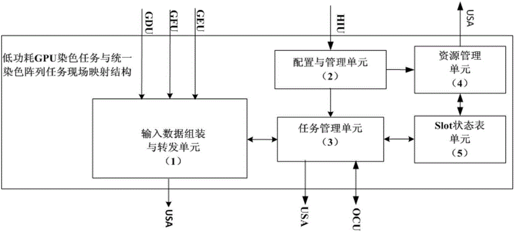
[0028] Such as figure 1 As shown, the overall block diagram of the architecture of the low-power GPU dyeing task and the unified dyeing array task site mapping structure, an input data assembly and forwarding unit (1), a configuration and management unit (2), and a task management unit (3) , a resource management unit (4), and a slot state table unit (5).

[0029] The specific structure and function of each module are introduced in detail below:

[0030] 1. Input data assembly and forwarding unit (1): It is the main component of the on-site mapping structure of the low-power GPU dyeing task and the unified dyeing array task, and is the hardware carrier for mapping the input data of the dyeing task to the localsram of the specified slot inside the USA. This module implements several functions, including:

[0031] 1.1. Vertex warp assembly: the external GDU (graphics drawing unit) and GFU (graphics function unit) provide the input attribute data of vertex, the input data width...


PUM


Abstract

The invention belongs to the field of GPU (Graphic Process Unit) design, and discloses a low power consumption GPU (Graphic Process Unit) staining task and uniform staining array task field mapping structure. The structure comprises an input data assembling and forwarding unit (1), a configuration and management unit (2), a task management unit (3), a resource management unit (4) and a slot state table unit (5), wherein the input data assembling and forwarding unit (1) receives vertex attribute data and Pixel attribute data input by an external module, assembles the vertex attribute data and the Pixel attribute data into Vertex warp and Pixel warp and forwards the Vertex warp and the Pixel warp a USA (Uniform Staining Array) task field; the configuration and management unit (2) receives a configuration parameter input by an external HIU (Host Interface Unit), and sets and records the value of the configuration parameter; the task management unit (3) executes idle slot query and task mapping, task output and task submission on the basis of a depth-first algorithm; the resource management unit (4) updates the resource management method of the slot according to the configuration parameter; and the slot state table unit (5) records the states and the task types of m pieces of slots (task fields) in the USA.

Description

technical field [0001] The invention belongs to the field of graphics processor design, and relates to a low-power consumption GPU dyeing task and a unified dyeing array task on-site mapping structure. Background technique [0002] Graphics processor (Graphic Process Unit, GPU) is an important part of modern computer hardware, and it is a key component for graphics drawing, processing and display. system. The GPU generates 2D and 3D graphics, images and videos to support visual computing such as window-based operating systems, graphical user interfaces, video games, visual image applications, and video playback. The graphics processing capability of GPU has been continuously improved with the widespread application of texture mapping technology. The high-speed pipeline, parallel features and flexible programmability of GPU provide a good operating platform for graphics processing and general parallel computing. [0003] At present, my country's GPU research and development...

Claims


Application Information

Patent Timeline
IPC IPC(8): G06T1/20G06F9/50
CPCG06F9/5066G06T1/20Y02D10/00
Inventor 田泽张骏郑新建任向隆马城城韩立敏
Owner XIAN AVIATION COMPUTING TECH RES INST OF AVIATION IND CORP OF CHINA
Learn More