
A design and type selection method for low-pressure flow and condenser of a double-backpressure steam turbine unit

A technology for steam turbine units and condensers, applied in instrumentation, calculation, geometric CAD, etc., can solve the problems of high heat consumption than design value, failure to fully utilize the performance of low-pressure cylinders, and failure to truly achieve optimal design, etc., to facilitate on-site layout , the effect of facilitating basic design

Inactive Publication Date: 2019-10-29
CHINA DATANG CORP SCI & TECH RES INST CO LTD EAST CHINA BRANCH
View PDF3 Cites 0 Cited by
  • Summary
  • Abstract
  • Description
  • Claims
  • Application Information

AI Technical Summary

Problems solved by technology

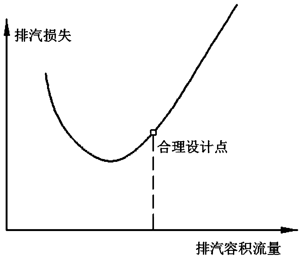
[0008] It can be seen from the above that when selecting the last-stage blades of the two low-pressure cylinders in the traditional double-back pressure unit, the same low-pressure final-stage blades are selected according to the principle of average back pressure. The difference in exhaust volume flow rate caused by the difference in pressure is 20% to 25%, that is, the exhaust residual velocity loss of the two low-pressure cylinders is not at the minimum point during actual operation, causing the actual heat consumption of the unit to be higher than the design value, and not fully utilized The performance of the low-pressure cylinder does not really achieve the purpose of optimal design

Method used


Image

  • A design and type selection method for low-pressure flow and condenser of a double-backpressure steam turbine unit
  • A design and type selection method for low-pressure flow and condenser of a double-backpressure steam turbine unit
  • A design and type selection method for low-pressure flow and condenser of a double-backpressure steam turbine unit

Examples


Embodiment Construction

[0051] The embodiments of the present invention are described in detail below. This embodiment is implemented on the premise of the technical solution of the present invention, and detailed implementation methods and specific operating procedures are provided, but the protection scope of the present invention is not limited to the following implementation example.

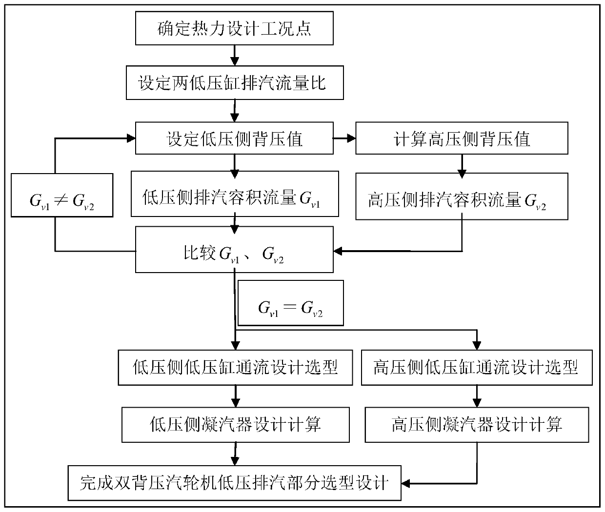
[0052] A design and type selection method for low-pressure flow and condenser of a double-backpressure steam turbine unit, the implementation flow chart is attached figure 2 shown. It includes the following steps:

[0053] 1. Determine the thermal design point of the steam turbine.

[0054] The thermal design point of the steam turbine is generally 100% of the rated load (base load unit), or 75% of the rated load (waist load unit) as the design point, and based on this, the optimal design is carried out. After determining the design working point, first calculate a preliminary scheme according to the traditiona...


PUM


Abstract

The invention discloses a double-backpressure turboset low-pressure through-flow and condenser selection design method. According to the method, thermodynamic design operating points of turbines are preset, the exhaust steam flow ratio of two low pressure cylinders is set, backpressure at the low pressure side is preset, and the exhaust steam volume flows of the low pressure cylinders at the low pressure side and the high pressure side are calculated according to the backpressure at the low pressure side; a preset value of the backpressure at the low pressure side is adjusted, and specifications of a last-stage blade with the minimum low pressure cylinder exhaust steam leaving-velocity loss are selected; the heat exchange area of condensers at the low pressure side and the high pressure side is calculated, and condenser specifications are selected according to the heat exchange area. Compared with the prior art, the method has the advantages that through non-equalization of mass flow of admission steam and exhaust steam of the two low pressure cylinders, the exhaust steam volume flows of the two low pressure cylinders are the same, and the exhaust steam leaving-velocity losses of the two low pressure cylinders are both minimum under the condition that the same last-stage blade is selected, that is, the sizes of steam exhaust ports of the low pressure cylinders are the same.

Description

technical field [0001] The invention relates to a method for design and type selection of low pressure cylinder flow and condenser of a steam turbine in a thermal power plant, in particular to a method for design and type selection of low pressure flow and condenser of a double back pressure steam turbine unit. Background technique [0002] At present, most of the four-row steam turbine units of 600MW and above in my country use double back pressure condensers, but in the traditional thermal system design and low pressure cylinder flow design, the design of single back pressure unit is still adopted, that is, two different The low-pressure cylinders with exhaust pressure are selected and designed according to the principle of equal flow and the average exhaust pressure as the back pressure. The double back pressure condenser is also designed and calculated according to the principle of equal heat load. [0003] Design features of traditional double back pressure unit: [000...

Claims


Application Information

Patent Timeline
Patent Type & Authority Patents(China)
IPC IPC(8): G06F17/50
CPCG06F30/17
Inventor 蒋寻寒陈开峰邵飞徐钟宇许昊煜王松浩阮圣奇吴仲胡中强任磊蒋怀锋陈裕
Owner CHINA DATANG CORP SCI & TECH RES INST CO LTD EAST CHINA BRANCH
Learn More