
Electro-optical logic NOR door

A technology of logic and NOT gates, applied in the field of electro-optical logic NOR gates, to achieve the effect of reducing requirements and insertion loss

Active Publication Date: 2017-05-10
SHANGHAI TECH UNIV
View PDF5 Cites 2 Cited by
  • Summary
  • Abstract
  • Description
  • Claims
  • Application Information

AI Technical Summary

Problems solved by technology

At present, there are few reports on this research

Method used


Image

  • Electro-optical logic NOR door
  • Electro-optical logic NOR door
  • Electro-optical logic NOR door

Examples


Embodiment Construction

[0024] In order to make the present invention more comprehensible, preferred embodiments are described in detail below with accompanying drawings.

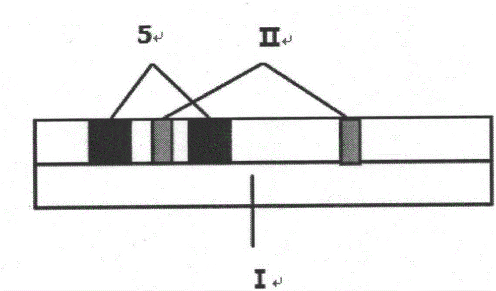
[0025] Such as figure 1 Shown, a kind of electro-optic logic NOR gate that the present invention provides is layered structure in vertical direction, and substrate 1 adopts the electro-optic crystal material of a whole block circle, rectangle, square or other shapes, is a pair of electrodes 5, Lightwavepath II and the rest of the cladding.

[0026] The electrode 5 adopts common metal materials such as aluminum, silver or copper (but not limited to aluminum, silver or copper).

[0027] Optical channel II constitutes three couplers—coupler one 1, coupler two 2 and coupler three 3. Coupler one 1 and coupler two 2 are single-wavelength couplers, using materials with photo-induced cut-off effect. Coupler 3 3 is a multi-wavelength coupler, using quartz material or other commonly used optical waveguide materials. Coupler one 1 and co...


PUM


Abstract

The invention provides an electro-optical logic NOR door. The electro-optical logic NOR door is characterized in that the electro-optical logic NOR door has two layers in the vertical direction, one layer is a base board, and the other layer comprises a pair of electrodes, light wave paths, and the rest of cladding, wherein the light wave paths constitute at least two couplers defined as the coupler 1 and the coupler 3 respectively, the coupler 1 achieves an electroinduced photorefractive effect by voltage control applied by the electrodes, and the coupler 3 transmits pumping light to achieve a light-induced truncation effect. The electroinduced photorefractive effect is combined with the light-induced truncation effect for the first time, and the electro-optical logic door needs no high power threshold requirement, is integrated, and complete logical operation of electrical signals and optical signals directly is obtained.

Description

technical field [0001] The invention relates to an electro-optic logic NOR gate based on electrorefraction and light-induced truncation, and belongs to the field of optoelectronic information, integrated optoelectronics and optoelectronic logic operation. Background technique [0002] At present, microprocessors composed of nano-transistors have been widely used in information technology fields such as computing, control and communication. Moreover, ultra-fast transistors based on 50nm processing technology have also been mass-produced, laying a solid foundation for further promoting the commercialization of ultra-fast computing. However, because the data transmission inside the processor and the data transmission between processors are severely restricted by the transmission rate of copper wires, the information delay is aggravated, which hinders the further development of digital circuits and forms the so-called "electronic bottleneck". In addition, although medium and lo...

Claims


Application Information

Patent Timeline
IPC IPC(8): G02F3/00
CPCG02F3/00
Inventor 陈直王雄毕凡王保胜徐丽凡巴钟灵
Owner SHANGHAI TECH UNIV
Learn More