
Manufacturing method of cantilever beam fiber grating accelerometer

A technology of acceleration sensor and optical fiber grating, which is applied in the direction of measurement of acceleration, velocity/acceleration/impact measurement, instruments, etc., can solve the problems of difficult maintenance, processing and handling, sensor deviation from the design value, easy damage of optical fiber grating, etc., to achieve changing sensitivity and Frequency range, strong practicability, and the effect of improving sensitivity

Active Publication Date: 2017-05-10
湖北三峡物联网知识产权运营有限公司
View PDF7 Cites 6 Cited by
  • Summary
  • Abstract
  • Description
  • Claims
  • Application Information

AI Technical Summary

Problems solved by technology

However, in the actual production process, due to the influence of fiber grating strain error, machining error of mechanical parts, structural assembly error, etc., the parameters of the sensor after assembly will deviate from the design value, and even cannot be used in serious cases, requiring rework and maintenance
However, because the fiber optic grating is easy to damage, and epoxy resin is often used to bond it to the mechanical structure, it is very easy to cause damage to the grating during maintenance and disassembly, and the sensor is mostly designed as a semi-closed structure with a narrow internal space, making maintenance, processing and handling very difficult

Method used

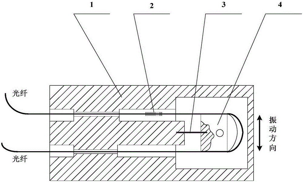
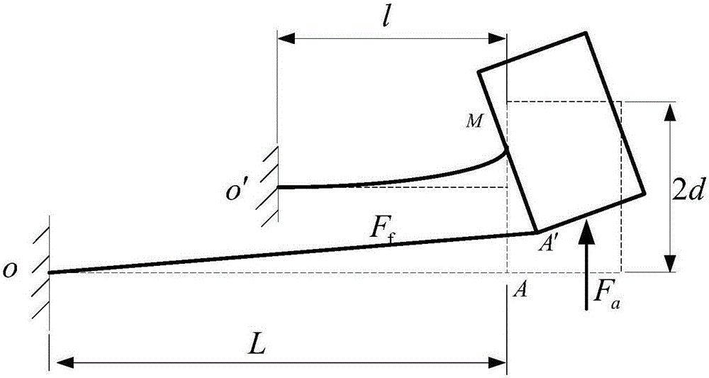
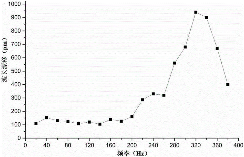

Image

  • Manufacturing method of cantilever beam fiber grating accelerometer
  • Manufacturing method of cantilever beam fiber grating accelerometer
  • Manufacturing method of cantilever beam fiber grating accelerometer

Examples


Embodiment Construction

[0028] Below in conjunction with accompanying drawing, specific embodiment of the present invention is described in further detail:

[0029] The cantilever beam fiber grating acceleration sensor described in this embodiment is used for geoacoustic monitoring of debris flow. Debris flow ground sound refers to that when a debris flow erupts, it carries a large amount of mud, sand, gravel and water during the movement and the collision and friction will cause the surface to vibrate. Studies have shown that the significant frequency of debris flow ground sound is 10-200Hz, and the typical intensity is 0.2m / s 2 Left and right, it is obviously different from the surface vibration signals produced by phenomena such as volcanic eruptions and earthquakes. By monitoring the ground sound of the debris flow and giving an alarm in the early stage of the debris flow, the loss of personnel and property caused by the debris flow can be effectively avoided or reduced. Fiber Bragg grating sen...


PUM

PropertyMeasurementUnit
Diameteraaaaaaaaaa
Thicknessaaaaaaaaaa

Abstract

The present invention provides a manufacturing method of a cantilever beam fiber grating accelerometer. The sensor comprises a substrate, a spring leaf, a quality block, a side cover and a fiber grating. The substrate, the spring leaf and the quality block are assembled through mechanical coordination and laser welding to form a cantilever structure. The fiber grating performs etching on the G.657 fiber, the fiber tension performance is improved through adoption of macromolecule ultrathin coating, and the epoxy resin dispensing is employed to fix the positions between the fiber grating and substrate and the quality block to assemble a fiber grating acceleration sensor. A balance weight hole is processed on the quality block in advance, the assembled sensor is calibrated, and the dispensing or machining is performed on the balance weight hole to flexibly regulate the sensitivity and the resonant frequency point of the sensor to optimize the performance index of the acceleration sensor. The manufacturing method of the cantilever beam fiber grating accelerometer simplifies the design and processing requirement of the acceleration sensor, simple in operation method and high in practicality, and the made sensor is high in sensitivity, small in insertion loss and excellent in performace.

Description

technical field [0001] The invention relates to the technical field of fiber grating applications, in particular to a method for manufacturing a cantilever beam type fiber grating acceleration sensor. Background technique [0002] Fiber Bragg grating sensing technology has the characteristics of high sensitivity, simple multiplexing, anti-electromagnetic interference, passive, etc., and is very popular in the field of acceleration sensors. At present, most fiber grating acceleration sensors use mechanical structures to increase sensitivity, convert acceleration changes into wavelength changes on fiber gratings, and then restore sensing information through grating demodulators. Such as the patent "A Cantilever Beam Type Fiber Bragg Grating Accelerometer" (Application No.: 200710065321.X), "Fiber Bragg Grating Accelerometer Based on Cantilever Beam Deflection" (Application No.: 200710065322.X), "Double Equal Intensity Cantilever Beam Fiber Grating Vibration Sensor" (Applicati...

Claims


Application Information

Patent Timeline
IPC IPC(8): G01P15/00
CPCG01P15/00
Inventor 罗志会王凤钧蔡德所陈思陈小刚潘礼庆肖焱山
Owner 湖北三峡物联网知识产权运营有限公司
Learn More