
Inner bore supersonic speed flame gun for liquid fuel

A supersonic flame, liquid fuel technology, applied in melting spraying, metal material coating process, coating and other directions, can solve the problems of unsatisfactory requirements, low flame speed, etc. The effect of reducing porosity

Active Publication Date: 2017-04-26
ZHENGZHOU LIJIA THERMAL SPRAYING MACHINERY CO LTD
View PDF6 Cites 6 Cited by
  • Summary
  • Abstract
  • Description
  • Claims
  • Application Information

AI Technical Summary

Problems solved by technology

[0004] The supersonic flame spray gun is generally used to spray the outer surface of the workpiece. For the narrow space with a diameter of less than 500mm, it is difficult to spray the inner surface of the narrow space with the conventional supersonic flame spray gun, because the flame of the conventional spray gun is sprayed axially and cannot change the direction of the flame. Direction and angle, so for inner wall or inner hole spraying, only special elbow inner hole spray gun can be used. The barrel of this spray gun has an angle of 60 degrees or 45 degrees with the combustion chamber. Flame spray guns use gas fuel, and the pressure of gas fuel is not high. When this spray gun burns, the combustion chamber pressure is low, and the flame speed formed is low. When spraying the inner wall of a relatively narrow pipe or the inner hole of some workpieces, the sprayed The particle speed is generally 500m / s, and the particles hit the surface of the workpiece to form a coating. For the coating that requires high bonding strength (greater than 80Mpa) and low porosity (less than 1%), this gas inner hole spray gun cannot meet the requirements

Method used


Image

  • Inner bore supersonic speed flame gun for liquid fuel

Examples


Embodiment Construction

[0019] Below in conjunction with accompanying drawing and specific embodiment, the present invention will be further explained and illustrated:

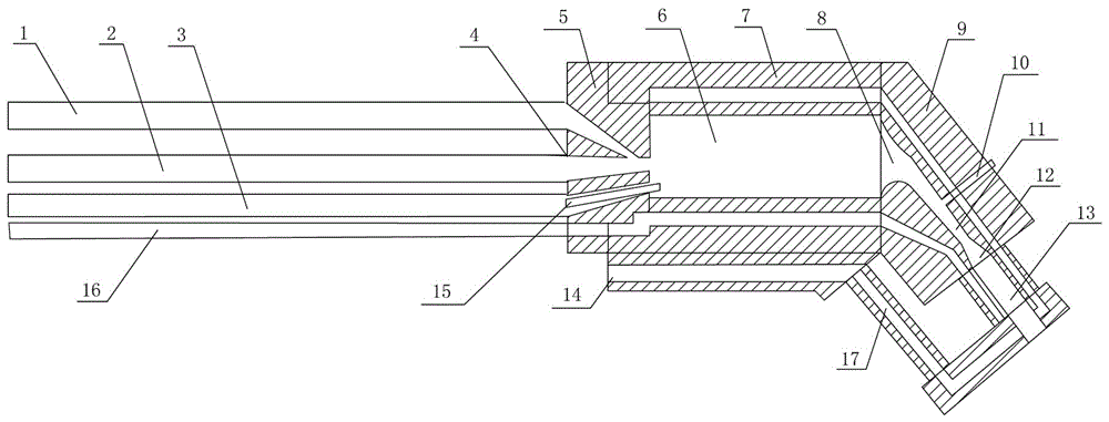
[0020] see figure 1 , a supersonic flame spray gun with a liquid fuel inner hole, including a gun casing 7 and a gun barrel 17 in the gun casing, and also includes an oxygen delivery pipeline 1, a fuel delivery pipeline 2, an ignition line pipeline 3, a fuel injection nozzle 4, and a stabilizer 5 , combustion chamber 6, high temperature and high pressure gas converging section 8, elbow connector 9, powder feeding needle 10, gas compression throat 11, flame diffusion section 12, nozzle 13, water outlet 14 at the bottom of the combustion chamber, spark plug 15 and cooling water inlet The water pipeline 16; the combustion chamber 6 is located in the inside of the gun housing 7, the fuel injection nozzle 4 is arranged at the position where the fuel delivery pipeline 2 is connected with the stabilizer 5, and the spark plug 15 is arranged ...


PUM


Abstract

The invention discloses an inner bore supersonic speed flame gun for a liquid fuel. The flame gun comprises a gun housing, a gun barrel, an oxygen conveying pipeline, a fuel conveying pipeline, an ignition line pipeline, a fuel spray nozzle, a stabilizer, a combustion chamber, a high-temperature high-pressure gas gathering section, an elbow connector, a power feeding needle, a gas compressing throat, a flame diffusion section, a nozzle, a bottom water outlet of the combustion chamber, a sparking plug and a cooling water inlet pipeline; the combustion chamber is located in the gun barrel, the fuel spray nozzle is arranged in a position where the fuel conveying pipeline and the stabilizer are connected, the sparking plug is arranged in a position where the ignition line pipeline is connected to the stabilizer, the stabilizer is arranged at one end of the combustion chamber while the elbow connector is arranged at the other end, the high-temperature high-pressure gas gathering section, the gas compression throat and the flame diffusion section are successively arranged in the through pipeline after the combustion chamber is connected to the elbow connector, and the nozzle is arranged at the tail end of the flame diffusion section; the power feeding port is located in the middle position of the elbow connector. The inner bore supersonic speed flame gun disclosed by the invention can effectively improve the flame speed and the bonding strength of the coating and reduce the porosity.

Description

[0001] Technical field: [0002] The invention relates to a flame spray gun, in particular to a liquid fuel inner hole supersonic flame spray gun, which adopts aviation kerosene fuel, can spray the inner wall of workpieces, and meets the coating requirements of high bonding strength. [0003] Background technique: [0004] The supersonic flame spray gun is generally used to spray the outer surface of the workpiece. For the narrow space with a diameter of less than 500mm, it is difficult to spray the inner surface of the narrow space with the conventional supersonic flame spray gun, because the flame of the conventional spray gun is sprayed axially and cannot change the direction of the flame. Direction and angle, so for inner wall or inner hole spraying, only special elbow inner hole spray gun can be used. The barrel of this spray gun has an included angle of 60 degrees or 45 degrees with the combustion chamber. Flame spray guns use gas fuel, and the pressure of gas fuel is not...

Claims


Application Information

Patent Timeline
IPC IPC(8): C23C4/129
Inventor 倪利民申忠王凯
Owner ZHENGZHOU LIJIA THERMAL SPRAYING MACHINERY CO LTD
Learn More