
Method for manufacturing injection molding rod

A manufacturing method and technology of injection molding rods, which are applied in the direction of household components, household appliances, and other household appliances, can solve the problems of lack of cushioning plastics, easily damaged screw teeth, and increased weight, so as to avoid waste of raw materials, enhance aesthetics, and increase effect of weight

Active Publication Date: 2017-04-26
李浩炜
View PDF3 Cites 0 Cited by
  • Summary
  • Abstract
  • Description
  • Claims
  • Application Information

AI Technical Summary

Problems solved by technology

However, the two ends of the injection rod in the prior art lack the coating of buffer plastic, which is easy to damage and produce screw holes during transportation, but the screw holes are easy to cause injury to personnel during use.
Moreover, the injection rod in the prior art is injected by setting thimbles at both ends of the original rod to resist or fix it by screws. After the injection molding is completed, process holes will be left at the two ends or the circumference of the injection rod. On the one hand, it affects Beautiful, on the other hand, the plastic will enter the steel pipe, resulting in increased weight and a waste of raw materials

Method used


Image

  • Method for manufacturing injection molding rod

Examples


Embodiment Construction

[0018] In order to make the object, technical solution and advantages of the present invention clearer, the present invention will be further described in detail below in conjunction with the accompanying drawings and specific embodiments. It should be understood that the specific embodiments described here are only used to explain the present invention, and are not intended to limit the present invention.

[0019] A method for making an injection molding rod, comprising the steps of:

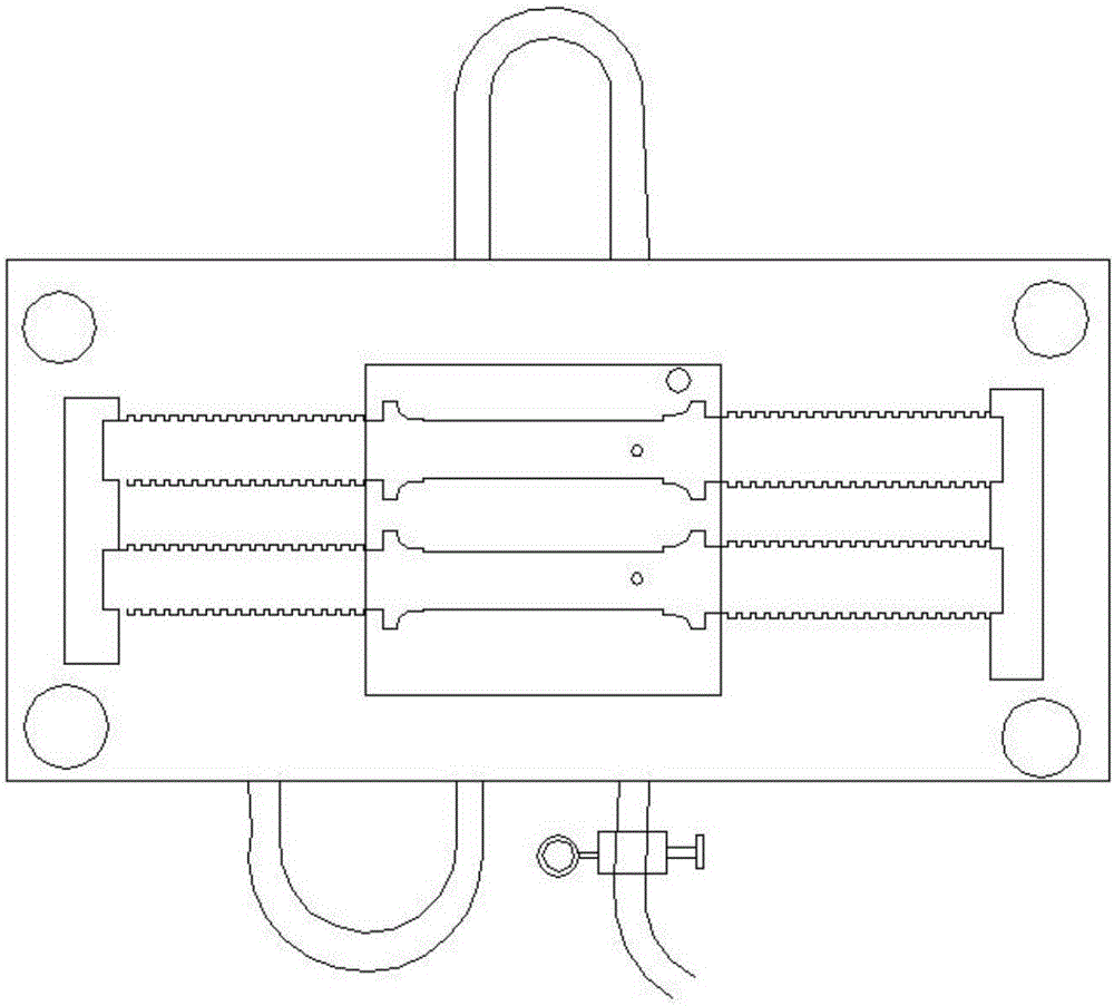
[0020] Step 1: making a mould, which includes a mold for the covers at both ends of the injection rod and a mold for the rod of the injection rod. Feasibly, the molds for the covers at both ends are cylindrical grooves, and the injection-molded covers are in the shape of hollow cylinders. see figure 1 , is a schematic diagram of the mold structure of the injection rod in this specific embodiment, which includes two cavities. In other specific embodiments of the present invention, multiple cav...


PUM


Abstract

The invention discloses a method for manufacturing an injection molding rod. The method comprises the steps that firstly, molds are manufactured and comprise the molds of covers at the two ends of the injection molding rod and the mold of a rod body of the injection molding rod; secondly, injection molding powder for the covers and the injection molding rod is prepared, and resin powder and an auxiliary which are pre-weighed are fully mixed; thirdly, the powder for injection molding of the covers is heated and molten, injection molding materials are injected into the compounded cover molds, natural cooling is carried out till forming is achieved, and the formed plastic covers are ejected out; fourthly, the formed covers are arranged on an original rod for the injection molding rod in a sleeving manner; and fifthly, the injection molding powder for the injection molding rod is heated and molten, the original rod sleeved with the covers is placed in the mold of the rod body of the injection molding rod for mold compounding, molten injection molding materials for the injection molding rod are injected, natural cooling is carried out till forming is achieved, and the formed injection molding rod is ejected out through an ejector pin. The method has the beneficial effects that plastic is prevented from entering a steel pipe in the injection molding process, no process hole is formed in the two ends and the peripheral ring of the injection molding rod after injection molding is completed, and corrosion can be avoided effectively.

Description

technical field [0001] The invention relates to a manufacturing process of sports equipment accessories, in particular to a manufacturing method of an injection molding rod. Background technique [0002] Injection rods are a type of accessories that are often used in sports equipment, and can be used as barbells, etc. The injection rod can effectively prevent the oxidation and corrosion of the round steel or steel pipe through thermoplastic plastic on the surface of the round steel or steel pipe, and can also play a certain buffering role. However, the two ends of the injection rod in the prior art lack the coating of cushioning plastic, which is easy to damage and produce screw holes during transportation, but the screw holes are easy to cause injury to personnel during use. Moreover, the injection rod in the prior art is injected by setting thimbles at both ends of the original rod to resist or fix it by screws. After the injection molding is completed, process holes will...

Claims


Application Information

Patent Timeline
IPC IPC(8): B29C45/14B29L31/52
CPCB29C45/14549B29C2045/1486B29C2045/14868B29L2031/52
Inventor 李峰李浩炜
Owner 李浩炜
Learn More