
Automatic bearing assembly machine

An automatic assembly machine and bearing technology, which is applied to assembly machines, metal processing equipment, manufacturing tools, etc., can solve the problems of low assembly efficiency, increased labor cost and time cost, and human resource consumption, so as to achieve improved efficiency, simple structure, The effect of increasing efficiency and automation

Active Publication Date: 2017-04-26
恩施市长源轴承制造有限公司
View PDF7 Cites 9 Cited by
  • Summary
  • Abstract
  • Description
  • Claims
  • Application Information

AI Technical Summary

Problems solved by technology

[0003] Most of the existing bearing assembly is carried out in sections, using semi-automatic operation. It is necessary to manually place the inner sleeve and the outer sleeve on the jig that cooperates with each other, and then press the ball into the gap between the two through the ball pressing device to complete the bearing. assembly, but the existing assembly efficiency is low, it needs to be assembled one by one, and manual loading and clamping are required at the same time, which greatly consumes human resources, thereby increasing the labor cost and time cost of assembly

Method used


Image

  • Automatic bearing assembly machine
  • Automatic bearing assembly machine
  • Automatic bearing assembly machine

Examples


Embodiment Construction

[0036] In order to enable those skilled in the art to better understand the technical solution of the present invention, the present invention will be described in detail below in conjunction with the accompanying drawings. The description in this part is only exemplary and explanatory, and should not have any limiting effect on the protection scope of the present invention. .

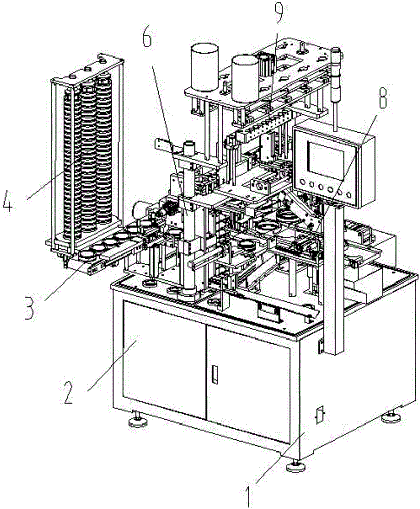
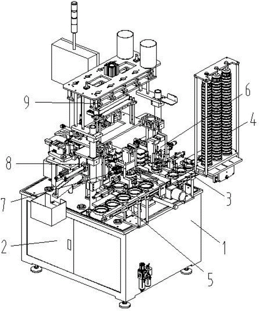
[0037] Such as Figure 1-Figure 9 As shown, the specific structure of the present invention is: an automatic bearing assembly machine, which includes a frame 1 and a power distribution control box 2, and the frame 1 is provided with a sleeve for fitting the outer sleeve 35 and the inner sleeve 12. The connecting device, the socketing device cooperates with the upper bead conveying groove 45 on the frame 1 through the feeding device 34, and the middle part of the upper bead conveying groove 45 is provided with a bead-pressing limit hole, and the bead-pressing limit hole The bead-pressing limiting devic...


PUM


Abstract

The invention relates to an automatic bearing assembly machine which comprises a machine frame and a power distribution control cabinet. The machine frame is provided with a muff-coupling device which is matched with an upper ball conveyor channel through a feeding device. A ball pressing limiting hole is formed in the middle of the upper ball conveyor channel. A ball pressing limiting device is arranged below the ball pressing limiting hole, and a ball pressing device is arranged above the ball pressing limiting hole. The ball pressing limiting device comprises a limiting base, and the limiting base is provided with a movable limiting air cylinder and a movable limiting base. The movable limiting base is provided with a limiting lifting air cylinder and a limiting ball-jacking block. The limiting ball-jacking block is annular and is in clearance fit with an inner sleeve and an outer sleeve. An inner sleeve clamping block matched with the inner side of the inner sleeve is further arranged in the middle of the limiting ball-jacking block. The muff-coupling device is arranged and matched with a ball pressing conveyor channel through the feeding device, the locations of the inner sleeve and the outer sleeve are controlled through the specific ball pressing limiting device, then the good ball pressing effect is achieved through the ball pressing device, automatic assembly is achieved, and the assembly efficiency is improved.

Description

technical field [0001] The invention relates to the field of bearing processing equipment, in particular to an automatic bearing assembly machine. Background technique [0002] With the advancement of mechanization, the application of bearings is becoming more and more extensive. It is widely used for the cooperation of various shaft parts. Bearings are generally composed of outer sleeves, inner sleeves and balls between them. Therefore, in the process of processing , often need to assemble them. [0003] Most of the existing bearing assembly is carried out in sections, using semi-automatic operation. It is necessary to manually place the inner sleeve and the outer sleeve on the jig that cooperates with each other, and then press the ball into the gap between the two through the ball pressing device to complete the bearing. assembly, but the existing assembly efficiency is low, it needs to be assembled one by one, and manual loading and clamping are required at the same tim...

Claims


Application Information

Patent Timeline
Patent Type & Authority Applications(China)
IPC IPC(8): B23P21/00
CPCB23P21/00B23P21/002
Inventor 邓君黄红梅邓凯李培
Owner 恩施市长源轴承制造有限公司
Learn More