Method for measuring thickness of slag floating on surface of molten metal
A technology of molten metal and measurement method, which is applied to measuring devices, instruments, and the use of wave/particle radiation, etc., can solve the problems of inability to measure the amount of slag in the tundish, lowering the yield of molten steel, and insufficient atmospheric blocking, and achieves suppression of The effect of slag entrapment
Inactive Publication Date: 2017-03-22
NIPPON STEEL CORP
View PDF6 Cites 7 Cited by
- Summary
- Abstract
- Description
- Claims
- Application Information
AI Technical Summary
Problems solved by technology
[0010] However, the method proposed in Patent Document 1 cannot measure the amount of slag in the tundish.
Therefore, when this method is applied to the supply of molten steel from the ladle to the tundish, there is a problem that when the closing operation of the sliding nozzle is carried out early in the continuous casting operation from the viewpoint of reliably preventing the molten slag from flowing out of the ladle , the residual molten steel in the ladle increases, and the yield of molten steel is greatly reduced
However, the measurement of the slag thickness using the measuring stick is a temporary measurement based on the operator's manual work, so there are problems in that there is a workload, the difference between the measured values of each operator is large, and continuous and stable measurement cannot be performed. to measure
[0013] And, also there is the following problem when the gauge rod is packed into molten steel: a part of the lid on the tundish upper surface must be opened, and the inert gas (such as Ar gas) environment in the tundish does not sufficiently block the atmosphere. The secondary oxidation caused by atmospheric intrusion leads to the generation of inclusions in the molten steel, which reduces the internal quality of the slab
The thickness of the slag flowing from the converter into the ladle is also measured using a gauge rod loaded by manual work in the same way as the thickness of the slag in the tundish, which becomes a burden on the operator
Method used
View moreImage
Smart ImageViewing Examples
Examples
Embodiment
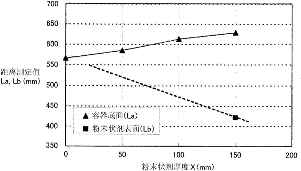
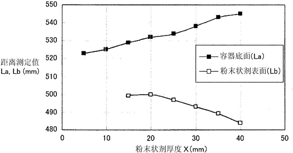
[0088] In order to confirm the effect of the slag thickness measurement method of the present invention, the following tests were conducted and the results were evaluated.
Login to View More PUM
| Property | Measurement | Unit |
|---|---|---|
| relative permittivity | aaaaa | aaaaa |
Abstract
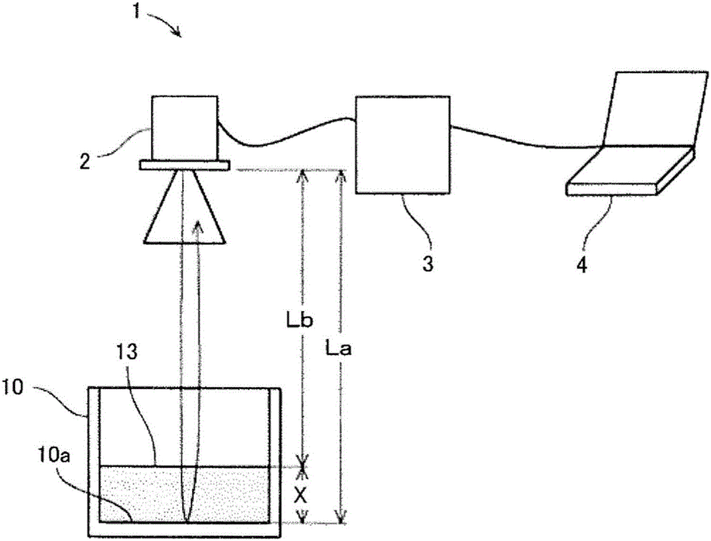
The primary purpose of this invention is to provide a method whereby the thickness of slag can be measured with a high degree of precision without depending on the operator. This invention uses a microwave distance meter that uses an antenna to emit and receive frequency-modulated microwaves that have a central frequency between 24 and 32 GHz and a frequency-modulation amplitude between 8 and 10 GHz. A first length of time from when the microwave distance meter emits the aforementioned microwaves to when microwaves reflected off the surface of a molten metal are received is computed, as is a second length of time from when the microwaves are emitted to when microwaves reflected off the surface of slag are received. A calculated value c(t1-t2) / 2 is computed from the first length of time t1, the second length of time t2, and the speed c of microwaves in air. A correction formula is obtained in advance from calculated-value measurement results from slag of previously-known thicknesses, and during operation, values obtained by using said correction formula to correct calculated values measured successively by the microwave distance meter are used as slag thicknesses.
Description
technical field [0001] The present invention relates to a method for measuring the thickness of slag suspended on the liquid surface of molten metal, and in particular to a slag thickness capable of continuously measuring the thickness of slag with high precision even when the thickness of the slag is thin test methods. Background technique [0002] In continuous casting of steel, molten steel is poured into a water-cooled mold and brought into contact with the mold to cool the molten steel, thereby forming a solidified shell while continuously drawing the solidified shell downward from the mold to produce a cast strand. [0003] In such continuous casting, a tundish is used as an intermediate container between a mold and a ladle for supplying molten steel to temporarily store molten steel when changing a ladle or to distribute molten steel to a plurality of molds. [0004] At the end of the operation of supplying the molten steel in the ladle to the tundish, a small amount...
Claims
Login to View More Application Information
Patent Timeline
 Patent Type & Authority Applications(China)
IPC IPC(8): G01B15/02
CPCG01B15/02
Inventor 村上敏彦水野泰宏
Owner NIPPON STEEL CORP
Features
- R&D
- Intellectual Property
- Life Sciences
- Materials
- Tech Scout
- Unparalleled Data Quality
- Higher Quality Content
- 60% Fewer Hallucinations
Learn More Browse by: Latest US Patents, China's latest patents, Technical Efficacy Thesaurus, Application Domain, Technology Topic, Popular Technical Reports.
© 2025 PatSnap. All rights reserved.Legal|Privacy policy|Modern Slavery Act Transparency Statement|Sitemap|About US| Contact US: help@patsnap.com


